~
SERVICE
MANUAL
move.
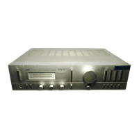
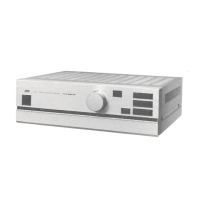
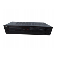
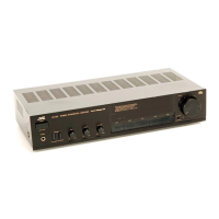
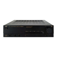
A-K100/A-K100B
|
_Model__|
Color
Version
_
A-K100
A-K100B
Contents
Page
Page
Safety
Precautions
................c:ccccecsssesececeeteetenenenenereees
1-1
A;
BlOCK
DiaQranny
ceisescccissccwccetieaguesaesanie
reson
1-5
Service
Precautions.
............ccccecccesseceescceseeeeeseeeeeeenaees
1-1
5.
Power
Amplifier
Idling
Current
Adjustment
1.
Specifications...........ccccccccccesesccecceeseseseseseseeeeeeseeees
1-2
PrOCCQUIES
nasheeds
neil
detonated
lesen
1-5
2.
Servicing
Method
For
AWG
#
20
Wires
6.
A-K100
Schematic
Diagram.............:c
eres
1-6
With
Clamping
Terminals...............:.:::cccceeeeeeeeees
1-2
7.
NVIOING
DidGral
Wii
ctaccantiniancccne
ems
1-7
3.
Removal
Procedures.
.............cccccccceeceeesesstreeeeeteeeees
1-3
Pants
bist.x.05.
sarc
Separate-vaume
Insertion
3-(1)
Metal
Cover
Section
.........cccccccccceeceseeeee
serene
1-3
3-(2)
Front
Panel
Section...................cccceeeeeeereeeeees
1-3
3-(3)
LED
Holder
Section................cccccecceeteeeee
eee
1-3
3-(4)
Level
Indicator
P.
C.
Board
Section..............
1-3
3-(5)
Power
Transistor
Replacement.................+
1-4
No.
2736
This
manual
combines
two
single
volumes;
Service
manual
and
Parts
list.
Jan.
1984