EasyManua.ls Logo

JVC KS-AX5700 User Manual

JVC KS-AX5700
33 pages
To Next Page IconTo Next Page
Page #1 background imageLoading...
Page #1 background image
SERVICE MANUAL
COPYRIGHT © 2005 Victor Company of Japan, Limited
No.MA195
2005/9
POWER AMPLIFIER
MA19520059
KS-AX5700
Lead free solder used in the board (material : Sn-Ag-Cu, melting point : 219 Centigrade)
TABLE OF CONTENTS
1 PRECAUTION. . . . . . . . . . . . . . . . . . . . . . . . . . . . . . . . . . . . . . . . . . . . . . . . . . . . . . . . . . . . . . . . . . . . . . . . . 1-2
2 SPECIFIC SERVICE INSTRUCTIONS . . . . . . . . . . . . . . . . . . . . . . . . . . . . . . . . . . . . . . . . . . . . . . . . . . . . . . 1-2
3 DISASSEMBLY . . . . . . . . . . . . . . . . . . . . . . . . . . . . . . . . . . . . . . . . . . . . . . . . . . . . . . . . . . . . . . . . . . . . . . . 1-3
4 ADJUSTMENT . . . . . . . . . . . . . . . . . . . . . . . . . . . . . . . . . . . . . . . . . . . . . . . . . . . . . . . . . . . . . . . . . . . . . . . . 1-6
5 TROUBLESHOOTING . . . . . . . . . . . . . . . . . . . . . . . . . . . . . . . . . . . . . . . . . . . . . . . . . . . . . . . . . . . . . . . . . . 1-8
Area suffix
J ------------- Northern America
E ------------- Southern Europe
U -------------------- Other Areas
w
w
w
.
x
i
a
o
y
u
1
6
3
.
c
o
m
Q
Q
3
7
6
3
1
5
1
5
0
9
9
2
8
9
4
2
9
8
T
E
L
1
3
9
4
2
2
9
6
5
1
3
9
9
2
8
9
4
2
9
8
0
5
1
5
1
3
6
7
3
Q
Q
TEL 13942296513 QQ 376315150 892498299
http://www.xiaoyu163.com
Question and Answer IconNeed help?

Do you have a question about the JVC KS-AX5700 and is the answer not in the manual?

JVC KS-AX5700 Specifications

General IconGeneral
BrandJVC
ModelKS-AX5700
CategoryAmplifier
LanguageEnglish

Summary

Section 1 Precaution

Safety Precautions

Important safety warnings and precautions for handling the equipment and preventing damage.

Section 2 Specific Service Instructions

Section 3 Disassembly

Main body

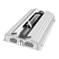
Procedures for disassembling the main body of the amplifier unit.

Section 4 Adjustment

Idling Current Adjustment

Steps and specifications for adjusting the idling current of the amplifier.

Test Point

Location and identification of test points for measurement and adjustment.

Section 5 Troubleshooting

Troubleshooting guide

Guide for diagnosing and resolving common issues and component replacement advice.

Schematic Diagrams

Block diagram

High-level overview of the amplifier's functional blocks and signal flow.

Standard schematic diagrams

Detailed electrical circuit diagrams for various sections of the amplifier.

Printed circuit boards

Layout diagrams of the main printed circuit boards for component identification.

Parts List

Exploded view of general assembly and parts list

Visual breakdown of the amplifier's parts with their corresponding numbers.

Electrical parts list

Comprehensive list of electrical components with part numbers and descriptions.

Packing materials and accessories parts list

List of packaging materials and included accessories for the product.

Related product manuals