EasyManua.ls Logo

JVC AX-222BK - User Manual

JVC AX-222BK
22 pages
Print Icon
To Next Page IconTo Next Page
Loading...
AX-222BK
JVC
SERVICE
MANUAL
AVG
aezze
srerconreararen
AMPLFER
Ope
Super
hs
Contents
Page Page
Safety
Precautions...
ces
eseeseessesseessseeseetseenaeeee
1-2
Adjustment
Procedufes
........ccceeeseestsesteseeteneenetes
1-10
SPECIFICATIONS:
«.ci5..cccccccessieacseapdecsteatbcecoeereeasesttveesesneceiens
1-3
Schematic
Diagram
..........eeeeeeseeeeeneeeeeeeeeeeeees
Insertion
Instruction
Book
1-4
Internal
Block
Diagrams
of
ICs..
..
Insertion
(
BlOCK:
DidQram
3
veieiseasicctendeascceescessessesei
cera
coveceacesseest
1-8
Connection
Diagram
...........ccceesseeseeeeeeeeeeeeees
Insertion
Removal
Procedures.........cccccccsccscceceeseeeeteenseeeseensenearees
1-9
Parts:
LIsts.ss:..-
ceca
esate
Separate
Volume
Insertion
No.
20025
Feb.
1988
Question and Answer IconNeed help?

Do you have a question about the JVC AX-222BK and is the answer not in the manual?

JVC AX-222BK Specifications

General IconGeneral
Total Harmonic Distortion (THD)0.03%
Weight6.5 kg
TypeIntegrated Amplifier
Frequency Response20 Hz - 20 kHz
Input Sensitivity150 mV
Signal-to-Noise Ratio95 dB
Speaker load impedance8 Ohm
Power Output30 watts per channel into 8Ω (stereo)

Summary

Safety Precautions

Warning

Important safety warnings and legal responsibilities for repair personnel.

Specifications

Front Panel Controls

Power Button Operation

Instructions for turning the unit on and off using the power button.

Speaker System Selection

How to select connected speaker systems or headphones for audio output.

Operation Guide

Listening Modes

Guides for listening to broadcasts, records, and tapes.

Other Operations

Instructions for headphone use and recording audio.

Block Diagram

Removal Procedures

Removing the Top Cover

Steps to remove the unit's top cover for internal access.

Removing the Front Panel

Instructions for safely removing the front panel assembly.

Removing the Power Transistors

Detailed steps for removing and replacing power transistors.

Installing the Volume Knob

Precautions and steps for correctly installing the volume knob.

Adjustment Procedures

Power Amplifier Idling Adjustment

Procedure for adjusting the power amplifier's idling current.

Schematic Diagram

Internal Block Diagrams of ICs

Connection Diagram

Parts List

Main Parts Locations

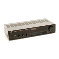
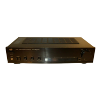
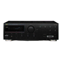
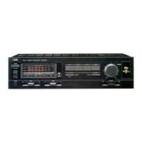
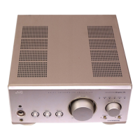
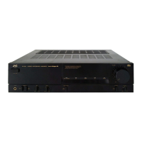
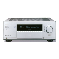
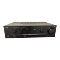
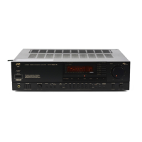
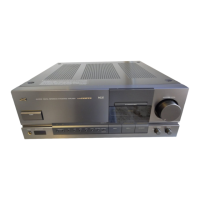
Identification of major components on the front, top, and rear views.

Exploded View and Part Numbers

Visual breakdown of the unit with corresponding part numbers.

Printed Circuit Board Assy and Parts List

Details on PCB assemblies and their constituent parts by area.

Accessories List

List of included accessories, manuals, and warranty cards.

Packing Materials and Part Numbers

Information regarding packaging materials and their part numbers.

Related product manuals