This document is a service manual for the JVC AX-242BK Stereo Integrated Amplifier. It provides comprehensive information for servicing, including technical specifications, operational instructions, disassembly procedures, adjustment guidelines, and parts lists.
Function Description:
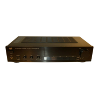
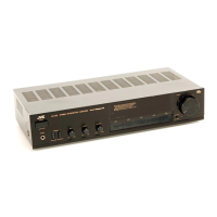
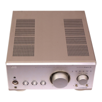
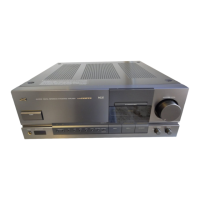
The JVC AX-242BK is a stereo integrated amplifier designed to amplify audio signals from various sources and drive loudspeakers. It features multiple input terminals for different audio components, including a turntable (PHONO), CD player (CD), tuner (TUNER), auxiliary devices (AUX), and tape decks (TAPE). The amplifier also includes output terminals for two sets of speakers (SYSTEM-1 and SYSTEM-2), a headphone jack for private listening, and AC outlets on the rear panel for connecting other audio components. Tone controls (BASS and TREBLE) and a balance control allow users to customize the sound output. A loudness control is provided to compensate for the ear's reduced sensitivity to low and high frequencies at low listening volumes. The amplifier incorporates a "Super A" circuit design, which is a JVC proprietary technology aimed at combining the advantages of Class A and Class B amplification to deliver high-quality sound with low distortion. Safety features are integrated into the design, including a protector IC (TA7317P) that monitors for DC voltage, overcurrent, and power ON/OFF conditions to protect the amplifier and connected speakers.
Important Technical Specifications:
- Output Power:
- 50 watts per channel into 8 ohms at 1 kHz (DIN).
- 40 watts per channel, min. RMS, both channels driven, into 8 ohms from 40 Hz to 20 kHz, with no more than 0.007% total harmonic distortion.
- 40 watts per channel, min. RMS, both channels driven, into 8 ohms at 1 kHz with no more than 0.003% total harmonic distortion (measured by JVC Audio Analyzer System).
- Total Harmonic Distortion: 0.007% (40 Hz - 20 kHz, 8 ohms) at 40 watts.
- Intermodulation Distortion: 0.007% (60 Hz: 7 kHz, 4:1, 8 ohms) at 40 watts.
- Power Bandwidth: 7 Hz - 50 kHz (IHF, 0.05%, 8 ohms both channels driven).
- Frequency Response: 5 Hz - 80 kHz +0, -3 dB (8 ohms).
- Damping Factor: 35 (1 kHz, 8 ohms).
- Input Sensitivity/Impedance (1 kHz):
- PHONO: 2.5 mV/47 kohms.
- CD/AUX/TUNER/TAPE: 200 mV/39 kohms.
- Signal-to-Noise Ratio ('66 IHF):
- PHONO: 71 dB.
- CD/AUX/TUNER/TAPE MONITOR: 104 dB.
- Signal-to-Noise Ratio ('78 IHF):
- PHONO (REC OUT): 78 dB.
- CD/AUX/TUNER/TAPE MONITOR (REC OUT): 78 dB.
- Signal-to-Noise Ratio (DIN):
- PHONO (SP OUT): 67 dB.
- CD/AUX/TUNER/TAPE MONITOR (SP OUT): 68 dB.
- Tone Controls:
- TREBLE: ±8 ±1 dB (at 10 kHz).
- BASS: ±8 ±1 dB (at 100 Hz).
- Loudness Controls (Volume control at -30 dB position): +6 dB (at 100 Hz), +4 dB (at 10 kHz).
- PHONO Overload Capacity: 90 mV (0.02% THD).
- PHONO RIAA Deviation: ±0.5 dB (20 Hz - 20 kHz).
- Recording Output Level/Impedance (TAPE REC): 200 mV/900 ohms.
- Dimensions (W x H x D): 435 x 102 x 252 mm (17-3/16" x 4-1/16" x 7-15/16").
- Weight: 5.0 kg (11.1 lbs).
- Power Consumption: 290 watts (U.K., Australia), 130 watts (Continental Europe, Other areas).
- Line Voltage & Frequency: AC 240 V~, 50 Hz (U.K., Australia); AC 230 V~, 50 Hz (Continental Europe); AC 110/127/220/240 V~ selectable, 50/60 Hz (Other areas).
Usage Features:
- Source Selection: An electronic source selector allows users to switch between PHONO, CD, TUNER, AUX, and TAPE inputs. The source indicator LEDs light up to show the selected input.
- Speaker Selection: The amplifier supports two sets of speakers (SYSTEM-1 and SYSTEM-2) which can be used individually or simultaneously. A headphone jack is available for private listening.
- Tape Monitoring: The TAPE MONITOR function allows users to listen to the sound being recorded on a 3-head tape deck in real-time.
- Recording Capability: Users can record from any selected source (PHONO, TUNER, CD, AUX) to a connected tape deck. The amplifier's VOLUME control does not affect the recording level, which must be adjusted via the tape deck's controls.
- Power Control: A POWER button on the front panel turns the unit ON/OFF. The SWITCHED AC outlets on the rear panel are controlled by this button, while the UNSWITCHED AC outlet remains ON regardless of the amplifier's power state.
- Voltage Selector: For models sold in "Other areas," a voltage selector allows adjustment to local AC supply voltages (110/127/220/240 V~). The fuse must be changed to the designated capacity when altering the voltage setting.
Maintenance Features:
- Safety Precautions: The manual emphasizes critical safety guidelines, including using identical replacement parts, avoiding unauthorized design alterations, observing original lead routing, and performing leakage current checks after re-assembly to prevent electric shock hazards.
- Disassembly Procedures: Detailed steps are provided for removing the top cover, front panel, and power transistors. This includes instructions on screw removal, handling plastic rivets, and unsoldering components.
- Idling Adjustment: A specific procedure is outlined for adjusting the idling current. This involves setting the volume to minimum, turning R751 and R752 fully counterclockwise, allowing the unit to warm up for at least 10 minutes, connecting a DC voltmeter to specific test points (R773 for left channel, R774 for right channel), and adjusting R751 or R752 until the voltmeter reads 11 mV ± 5 mV.
- Internal Block Diagrams: Block diagrams for key integrated circuits, such as the TA7317P (Protector IC) and LC7818 (Analog Switch), are provided to aid in troubleshooting and understanding circuit functionality. The VC5022 (Super A IC) block diagram is also included.
- Schematic Diagrams and Printed Circuit Board Layouts: These are provided as insertions, offering detailed circuit information and component placement for repair and diagnosis.
- Parts List: A comprehensive list of all components, including part numbers, descriptions, quantities, and applicable areas (e.g., U.K., Australia, Continental Europe, Universal Type), is included to facilitate ordering and replacement of parts. Safety-critical components are marked with a triangle (▲) and shaded in the schematic diagrams.