Do you have a question about the JVC AX-V4BK and is the answer not in the manual?
Instructions and precautions before installing the unit.
Verifying all included accessories are present before setup.
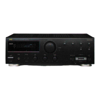
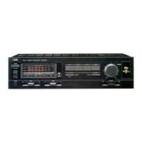
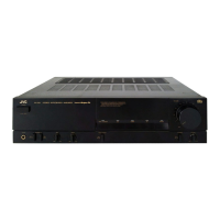
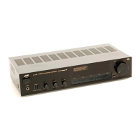
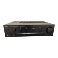
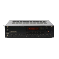
Overview of buttons and controls on the front of the unit.
Description of buttons and functions on the remote control.
How to connect front speakers, including impedance considerations.
Guide for connecting rear and center speakers for surround sound.
Connecting various audio and video sources using RCA plugs.
Connecting components for JVC's COMPU LINK-3 remote control.
Using the unit's AC outlet to power other components.
How to turn the unit on/off and select audio/video sources.
Advanced operation for selecting different sources for audio and video.
Adjusting the main volume and using the loudness function.
Adjusting front speaker balance and bass/treble tone.
Using the mute function and connecting headphones.
Explanation of direct sound and reflections in acoustic surround.
How to use JVC's proprietary Hall Surround mode.
Overview of Dolby Pro Logic and Dolby 3ch Logic surround modes.
Selecting surround programs and center modes for Dolby Surround.
Adjusting delay times and using the test tone for surround calibration.
Solutions for display not lighting up or no sound from speakers.
Troubleshooting single-speaker sound or howling during playback.
Resolving problems with the remote control not working or weak batteries.
Details on power output for front, center, and rear channels.
Technical specs for frequency response, input sensitivity, and impedance.
Power requirements, consumption, dimensions, and mass of the unit.
Pin layout and key matrix for the main system controller IC.
Detailed description of each pin's function for the system controller.
Pin configuration for the Dolby Pro Logic Surround Signal Processor.
Detailed functions for each pin of the LA2785 IC.
Illustrates the path of audio and video signals through the unit.
Diagram showing the control circuitry and system controller interface.
Block diagram of the power supply circuitry and its components.
Detailed circuit diagram for the source selection section.
Circuit diagram for the surround processing and control logic.
Detailed circuit diagram for the power amplifier stages.
Layout and component list for the system control PC board.
Layout and component list for the power amplifier PC board.
Exploded view showing component placement and associated parts list.
| Total Harmonic Distortion | 0.007% |
|---|---|
| Input Sensitivity | 2.5mV (MM), 200mV (line) |
| Speaker load impedance | 8 ohms |
| Dimensions | 435 x 148 x 388mm |
| Weight | 10.4kg |
| Signal-to-Noise Ratio | 100dB (line) |
| Output power per channel | 40W (8 ohms, 20Hz-20kHz, 0.08% THD) |