EasyManua.ls Logo

JVC AV-20N3 User Manual

JVC AV-20N3
32 pages
To Next Page IconTo Next Page
Page #1 background imageLoading...
Page #1 background image
No. 52025
Jun. 2002
AV-20N3
AV-20NMG
3
AV-20NMG3
B
1
COPYRIGHT © 2002 VICTOR COMPANY OF JAPAN, LTD.
AV-20N3/AV-20N3
/D
AV-20NMG3/AV-20NMG3B
/AV-20NMG3
/-A
CONTENTS
!
SPECIFICATIONS
・・・・・・・・・・・・・・・・・・・・・・・・・・・・・・
・・・・・・・・・・・・・・・・・・・・・・・・・・・・・・・・・・・・・・・・・・・・・・・・・・・・・・・・・・・・
・・・・・・・・・・・・・・・・・・・・・・・・・・・・・・・・・・・・・・・・・・・・・・・・・・・・・・・・・
・・・・・・・・・・・・・・・・・・・・・・・・・・・・・・・・・・・・・・・・・・・・・・・・・・・・・・
・・・・・・・・・・・・・・・・・・・・・・・・・・・
2
!
SAFETY PRECAUTIONS ・・・・・・・・・・・・・・・・・・・・・・・・・・・・・・
・・・・・・・・・・・・・・・・・・・・・・・・・・・・・・・・・・・・・・・・・・・・・・・・・・・・・・・・・・・・
・・・・・・・・・・・・・・・・・・・・・・・・・・・・・・・・・・・・・・・・・・・・・・・・・・・
・・・・・・・・・・・・・・・・・・・・・・・・・・・・・・・・・・・・・・・・・・
・・・・・・・・・・・・・・・・・・・・・ 3
!
FEATURES・・・・・・・・・・・・・・・・・・・・・・・・・・・・・・
・・・・・・・・・・・・・・・・・・・・・・・・・・・・・・・・・・・・・・・・・・・・・・・・・・・・・・・・・・・・
・・・・・・・・・・・・・・・・・・・・・・・・・・・・・・・・・・・・・・・・・・・・・・・・・・・・・・・・・・・・
・・・・・・・・・・・・・・・・・・・・・・・・・・・・・・・・・・・・・・・・・・・・・・・・・・・・・・・・・・・・
・・・・・・・・・・・・・・・・・・・・・・・・・・・・・・・・
・・・・
・・ 4
!
FUNCTIONS ・・・・・・・・・・・・・・・・・・・・・・・・・・・・・・
・・・・・・・・・・・・・・・・・・・・・・・・・・・・・・・・・・・・・・・・・・・・・・・・・・・・・・・・・・・・
・・・・・・・・・・・・・・・・・・・・・・・・・・・・・・・・・・・・・・・・・・・・・・・・・・・・・・・・・・・・
・・・・・・・・・・・・・・・・・・・・・・・・・・・・・・・・・・・・・・・・・・・・・・・・・・・・・・・・・・・・
・・・・・・・・・・・・・・・・・・・・・・・・・・・・・・
・・・・
・・ 5
!
MAIN DIFFERENCE LIST ・・・・・・・・・・・・・・・・・・・・・・・・・・・・・・
・・・・・・・・・・・・・・・・・・・・・・・・・・・・・・・・・・・・・・・・・・・・・・・・・・・・・・・・・・・・
・・・・・・・・・・・・・・・・・・・・・・・・・・・・・・・・・・・・・・・・・・・・・・・・・・・
・・・・・・・・・・・・・・・・・・・・・・・・・・・・・・・・・・・・・・・・・・
・・・・・・・・・・・・・・・・・・・・・ 7
! SPECIFIC SERVICE INSTRUCTIONS ・・・・・・・・・・・・・・・・・・・・・・・・・・・・・・
・・・・・・・・・・・・・・・・・・・・・・・・・・・・・・・・・・・・・・・・・・・・・・・・・・・・・・・・・・・・
・・・・・・・・・・・・・・・・・・・・・・・・・・・・・・・・・・・・・・・・・
・・・・・・・・・・・・・・・・・・・・・・
・・・・・・・・・・・ 8
!
SERVICE ADJUSTMENTS
・・・・・・・・・・・・・・・・・・・・・・・・・・・・・・
・・・・・・・・・・・・・・・・・・・・・・・・・・・・・・・・・・・・・・・・・・・・・・・・・・・・・・・・・・・・
・・・・・・・・・・・・・・・・・・・・・・・・・・・・・・・・・・・・・・・・・・・・・・・・・
・・・・・・・・・・・・・・・・・・・・・・・・・・・・・・・・・・・・・・
・・・・・・・・・・・・・・・・・・・
15
!
PARTS LIST ・・・・・・・・・・・・・・・・・・・・・・・・・・・・・・
・・・・・・・・・・・・・・・・・・・・・・・・・・・・・・・・・・・・・・・・・・・・・・・・・・・・・・・・・・・・
・・・・・・・・・・・・・・・・・・・・・・・・・・・・・・・・・・・・・・・・・・・・・・・・・・・・・・・・・・・・
・・・・・・・・・・・・・・・・・・・・・・・・・・・・・・・・・・・・・・・・・・・・・・・・・・・・・・・・・・・・
・・・・・・・・・・・・・・・・・・・・・・・・・・・・・・
33
OPERATING INSTRUCTIONS
STANDARD CIRCUIT DIAGRAM ・・・・・・・・・・・・・・・・・・・・・・・・・・・・・・
・・・・・・・・・・・・・・・・・・・・・・・・・・・・・・・・・・・・・・・・・・・・・・・・・・・・・・・・・・・・
・・・・・・・・・・・・・・・・・・・・・・・・・・・・・・・・・・・・・・・・・・・・・
・・・・・・・・・・・・・・・・・・・・・・・・・・・・・・
・・・・・・・・・・・・・・・ 2-1
SERVICE MANUAL
COLOUR TELEVISION
BASIC CHASSIS
CG
[
RM-C36 4G Y ]
[ RM-C364 ]
Question and Answer IconNeed help?

Do you have a question about the JVC AV-20N3 and is the answer not in the manual?

JVC AV-20N3 Specifications

General IconGeneral
Display TechnologyCRT
Screen Size20 inches
Aspect Ratio4:3
Audio OutputMono
Resolution480i
Inputs/OutputsComposite video input, RF input
InputsComposite, RF
Speakers1

Summary

Specifications

Safety Precautions

Isolation Check

Checks for electrical shock hazard using dielectric strength and leakage current tests.

Features

System Block Diagram

Diagram illustrating the main components and their interconnections in the TV system.

Functions

Front and Rear Panel Functions

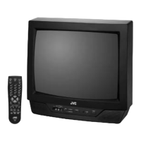
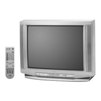
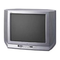
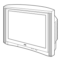
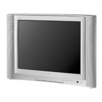
Identifies and describes the buttons, terminals, and lamps on the front and rear of the TV set.

Remote Control Unit

Remote Control Unit Operation

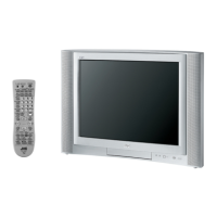
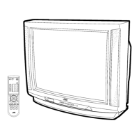
Details the functions and key assignments of the remote control unit for TV operation.

Main Difference List

Specific Service Instructions

Disassembly and Wire Management

Step-by-step guide for disassembling the TV, managing wires, and checking internal components.

Replacement of Memory ICs

Memory ICs Replacement Procedure

Detailed steps for replacing memory integrated circuits, including system constant setting.

System Constant and User Setting Values

Setting of System Constant Set

Defines initial system constant values for various TV models.

User Setting Values

Lists user-configurable settings and their default values.

Initial Service Menu Settings

V/C, Deflection, and VSM Preset Settings

Provides initial setting values for Video/Chroma, Deflection, and VSM presets via the service menu.

Preset Adjustments

IC301 Replacement (IF V/C Decoder)

IC Replacement Procedures

Steps for replacing the IF V/C DECODER IC, including data transfer and panel location.

Service Adjustments Overview

Preparation for Adjustment

Prerequisites, required instruments, and general guidelines before performing service adjustments.

Basic Service Menu Operation

Service Menu Operation Guide

Explains the service menu structure, adjustment items, and key operations.

Service Menu Setting Procedures

IF, VCO, Delay Point Settings

Procedures for adjusting IF, VCO, and Delay Point settings in the service menu.

V/C, DEF, VSM Preset Settings

Procedures for adjusting V/C, DEF, and VSM PRESET settings.

Setup Tour Procedure

Procedure for setting up the TV, including language and auto search.

Service Menu Flow Charts

Sub Menus for IF, V/C, DEF, VSM Preset, Preset

Flowcharts illustrating the structure and sub-menus for various service adjustments.

Adjustment Locations

Test Points and Component Diagrams

Diagrams showing test points and component locations on the CRT socket and main PWB.

Core Adjustments

B1 Power Supply and Focus Adjustment

Procedures for adjusting B1 Power Supply voltage and picture focus.

IF Circuit Adjustment

Procedure for adjusting the IF circuit, focusing on VCO settings.

IF Circuit Delay Point Adjustment

Delay Point (AGC Take-over) Adjustment

Procedure for adjusting the Delay Point and AGC Take-over settings in the IF circuit.

Video/Chroma Circuit Adjustments

White Balance and Drive Adjustments

Adjustments for white balance (low light) and drive levels (R, B) in the video/chroma circuit.

Video/Chroma Brightness, Contrast, and Colour Adjustments

Brightness and Contrast Adjustment

Procedures for adjusting brightness and contrast in the video/chroma circuit.

Colour Settings Adjustment

Adjusting colour settings for PAL, SECAM, and NTSC signals.

Video/Chroma Colour II Adjustments

Detailed Colour Adjustments

Detailed colour adjustments using measuring instruments for PAL, SECAM, and NTSC signals.

Tint Adjustments

NTSC Tint Adjustment

Procedures for adjusting NTSC tint, both with and without measuring instruments.

SECAM Black Offset Adjustment

SECAM Black Offset Adjustment

Procedure for adjusting the black offset for SECAM signals.

Deflection Circuit Adjustments

Vertical and Horizontal Positioning

Adjusting vertical height, position, and horizontal position in the deflection circuit.

Deflection and VSM Preset Settings

Vertical Linearity and Curve Adjustment

Adjusting vertical linearity and curvature in the deflection circuit.

VSM Preset Settings

Setting VSM presets for different modes like Bright, Standard, and Soft.

Purity and Convergence Adjustment

Purity Adjustment

Procedure for adjusting the purity of the CRT display.

Convergence Adjustment Details

Static and Dynamic Convergence Adjustment

Procedures for static and dynamic convergence adjustment using magnets and yoke movement.

Chip Component Replacement

Chip Component Replacement Guide

Guide covering cautions, soldering iron use, and step-by-step replacement of chip components.

Related product manuals