EasyManua.ls Logo

JVC AV-20320/S - User Manual

JVC AV-20320/S
42 pages
Print Icon
To Next Page IconTo Next Page
Loading...
No.51964
Mar. 2002
A
V-20320
A
V-20321
1
COPYRIGHT © 2002 VICTOR COMPANY OF JAPAN, LTD.
Mar. 2002
AV-20320
/S
AV-20321
/S
CONTENTS
SPECIFICATIONS
]]]]]]]]]]]]]]]]]]]]]]]]]]]]]]]]
]]]]]]]]]]]]]]]]]]]]]]]]]]]]]]]]]]]]]]]]]]]]]]]]]]]]]]]]]]]]]]]]
]]]]]]]]]]]]]]]]]]]]]]]]]]]]]]]]]]]]]]]]]]]]]]]]]]]]]]]]]]]]]
]]]]]]]]]]]]]]]]]]]]]]]]]]]]]]]]]]]]]]]]]]]]]]]]]]]]]]]]]]
]]]]]]]]]]]]]]]]]]]]]]]]]]]]]
2
SAFETY PRECAUTIONS
]]]]]]]]]]]]]]]]]]]]]]]]]]]]]]]]
]]]]]]]]]]]]]]]]]]]]]]]]]]]]]]]]]]]]]]]]]]]]]]]]]]]]]]]]]]]]]]]]
]]]]]]]]]]]]]]]]]]]]]]]]]]]]]]]]]]]]]]]]]]]]]]]]]]]]]]]
]]]]]]]]]]]]]]]]]]]]]]]]]]]]]]]]]]]]]]]]]]]]]]
]]]]]]]]]]]]]]]]]]]]]]]
3
FEATURES
]]]]]]]]]]]]]]]]]]]]]]]]]]]]]]]]
]]]]]]]]]]]]]]]]]]]]]]]]]]]]]]]]]]]]]]]]]]]]]]]]]]]]]]]]]]]]]]]]
]]]]]]]]]]]]]]]]]]]]]]]]]]]]]]]]]]]]]]]]]]]]]]]]]]]]]]]]]]]]]]]]
]]]]]]]]]]]]]]]]]]]]]]]]]]]]]]]]]]]]]]]]]]]]]]]]]]]]]]]]]]]]]]]]
]]]]]]]]]]]]]]]]]]]]]]]]]]]]]]]]]]]
]]]]]]
]]]
4
MAIN DIFFERENCE LIST
]]]]]]]]]]]]]]]]]]]]]]]]]]]]]]]]
]]]]]]]]]]]]]]]]]]]]]]]]]]]]]]]]]]]]]]]]]]]]]]]]]]]]]]]]]]]]]]]]
]]]]]]]]]]]]]]]]]]]]]]]]]]]]]]]]]]]]]]]]]]]]]]]]]]]]]]]
]]]]]]]]]]]]]]]]]]]]]]]]]]]]]]]]]]]]]]]]]]]]]]
]]]]]]]]]]]]]]]]]]]]]]]
5
SPECIFIC SERVICE INSTRUCTIONS
]]]]]]]]]]]]]]]]]]]]]]]]]]]]]]]]
]]]]]]]]]]]]]]]]]]]]]]]]]]]]]]]]]]]]]]]]]]]]]]]]]]]]]]]]]]]]]]]]
]]]]]]]]]]]]]]]]]]]]]]]]]]]]]]]]]]]]]]]]]]]]]
]]]]]]]]]]]]]]]]]]]]]]]]]]
]]]]]]]]]]]]]
6
SERVICE ADJUSTMENTS
]]]]]]]]]]]]]]]]]]]]]]]]]]]]]]]]
]]]]]]]]]]]]]]]]]]]]]]]]]]]]]]]]]]]]]]]]]]]]]]]]]]]]]]]]]]]]]]]]
]]]]]]]]]]]]]]]]]]]]]]]]]]]]]]]]]]]]]]]]]]]]]]]]]]]]]
]]]]]]]]]]]]]]]]]]]]]]]]]]]]]]]]]]]]]]]]]]
]]]]]]]]]]]]]]]]]]]]]
11
PARTS LIST
]]]]]]]]]]]]]]]]]]]]]]]]]]]]]]]]
]]]]]]]]]]]]]]]]]]]]]]]]]]]]]]]]]]]]]]]]]]]]]]]]]]]]]]]]]]]]]]]]
]]]]]]]]]]]]]]]]]]]]]]]]]]]]]]]]]]]]]]]]]]]]]]]]]]]]]]]]]]]]]]]]
]]]]]]]]]]]]]]]]]]]]]]]]]]]]]]]]]]]]]]]]]]]]]]]]]]]]]]]]]]]]]]]]
]]]]]]]]]]]]]]]]]]]]]]]]]]]]]]]]]
]]
]
27
Ӡ
OPERATING INSTRUCTIONS
Ӡ
STANDARD CIRCUIT DIAGRAM
]]]]]]]]]]]]]]]]]]]]]]]]]]]]]]]]
]]]]]]]]]]]]]]]]]]]]]]]]]]]]]]]]]]]]]]]]]]]]]]]]]]]]]]]]]]]]]]]]
]]]]]]]]]]]]]]]]]]]]]]]]]]]]]]]]]]]]]]]]]]]]]]]]
]]]]]]]]]]]]]]]]]]]]]]]]]]]]]]]]
]]]]]]]]]]]]]]]]
2-1
SERVICE MANUAL
COLOR TELEVISION
BASIC CHASSIS
FV5
Question and Answer IconNeed help?

Do you have a question about the JVC AV-20320/S and is the answer not in the manual?

Overview

This document provides service information for the JVC AV-20320/S and AV-20321/S color televisions, including specifications, features, adjustment procedures, and parts lists.

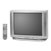
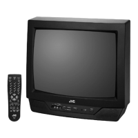
The JVC AV-20320/S and AV-20321/S are color televisions designed with a new chassis for simplified circuitry, utilizing a single board. They are equipped with a miniature tuner for both TV and CATV reception. The televisions feature a multifunctional remote control that allows for picture adjustment. A notable usage feature is the "CHANNEL GUARD" function, which prevents the selection of specific channels unless a designated "ID number" is entered. The internal control system relies on I2C bus control, implemented with single-chip ICs.

Key usage features include the "VIDEO STATUS" function, "ON/OFF TIMER" function, and "HYPER SURROUND" function for enhanced audio. The televisions are fitted with a common 75Ω V/U (F-Type) ANT Terminal for antenna connection. A "SLEEP TIMER" allows for real-time setting of a sleep duration. Closed-caption broadcasts can be viewed, and the units include an Audio Video input terminal and a Variable Audio output terminal. An integrated MTS (Multi-Channel Television Sound) system is also built-in.

Important Technical Specifications:

  • Dimensions (W x H x D): 19-7/8" x 17-7/8" x 19-1/2" / 50.3cm x 45.2cm x 49.3cm
  • Mass: 43.8 lbs / 19.9 kg
  • TV RF System: CCIR(M)
  • Color Sound System: NTSC/BTSC System (Multi Channel Sound)
  • TV Receiving Channels and Frequency:
    • VL Band: (02~06) 54MHz~88MHz
    • VH Band: (07~13) 174MHz~216MHz
    • UHF Band: (14~69) 470MHz~806MHz
  • CATV Receiving Channels and Frequency:
    • Low Band: (02~06, A-8) by (02~06&01)
    • High Band: (07~13) by (07~13)
    • Mid Band: (A~I) by (14~22)
    • Super Band: (J~W) by (23~36)
    • Hyper Band: (W+1~W+28) by (37~64)
    • Ultra Band: (W+29~W+84) by (65~125)
    • Sub Mid Band: (A8, A4~A1) by (01, 96~99)
    • TV/CATV Total Channel: 180 Channels
    • Overall CATV Frequency Range: (54MHz~804MHz)
  • Intermediate Frequency:
    • Video IF Carrier: 45.75MHz
    • Sound IF Carrier: 41.25MHz (4.5MHz)
    • Color Sub Carrier: 3.58MHz
  • Power Input: 120V AC, 60Hz
  • Power Consumption: 87W (US) / 1.4A (CA)
  • Picture Tube: 20" (51cm) Measured Diagonally
  • High Voltage: 26.5kV±1kV (at zero beam current)
  • Speaker: 2" x 3-1/2" / 5 x 9cm Oval type x 2
  • Audio Power Output: 1W+1W
  • Input:
    • Video Input: 1Vp-p, 75Ω (RCA pin jack)
    • Audio Input: 500mVrms (-4dBs), High Impedance (RCA pin jack)
  • Fix Audio Output: 500mVrms(-4dBs), Low impedance (400Hz when modulated 100%) (RCA pin jack)
  • Headphone Jack: 3.5mm stereo mini jack (Sound is stereo)
  • Antenna Terminal: 75Ω (VHF/UHF) Terminal, F-Type Connector
  • Remote Control Unit: RM-C205-1C (AV-20320/S), RM-C205W-1C (AV-20321/S) (AA/R6/UM-3 battery x 2)

Maintenance Features:

The manual outlines several maintenance and adjustment procedures.

Safety Precautions:

The document emphasizes safety during service, including the use of specified replacement parts, proper handling of components, and adherence to safety checks like isolation transformer usage, dielectric strength tests, and leakage current measurements. It highlights the importance of using an isolation transformer when the chassis is hot and connected to the AC power line. It also details procedures for checking the live side and isolated neutral side of the power circuit.

Disassembly Procedure:

Instructions are provided for removing the rear cover, main PW board, and speaker. This includes specific screw locations and cautions for handling components.

Memory IC Replacement:

This model uses a memory IC that stores data for proper operation of video and deflection circuits. The replacement procedure involves:

  1. Power off: Disconnecting the power cord.
  2. Replace the memory IC: Ensuring the new IC has the initial value entered.
  3. Power on: Reconnecting the power cord.
  4. System constant check and setting: Accessing the SERVICE MENU and SYSTEM CONSTANT screen using specific remote control key combinations (SLEEP TIMER, DISPLAY, VIDEO STATUS). Settings are adjusted using MENU UP/DOWN and LEFT/RIGHT keys.
  5. Receive channel setting: Setting channels according to the operating instructions.
  6. User settings: Checking and adjusting user settings.
  7. SERVICE MENU setting: Verifying and setting necessary items in the SERVICE MENU.

Replacement of Chip Components:

Detailed instructions are given for replacing chip components, including cautions for soldering (avoiding overheating, using appropriate solder, and not reusing chip parts) and specific steps for removing and installing resistors, capacitors, transistors, and diodes using tweezers and soldering irons.

Service Adjustments:

A comprehensive section covers various adjustments, including:

  • B1 Power Supply: Checking the DC voltage at specific test points (TP-91 (B1) and TP-E (⊥)) to ensure it is within the specified range (DC134V +2V/-2.5V).
  • Video / Def. Circuit Adjustments:
    • IF VCO Adjustment: Adjusting the CW TRANSF. (T131) in [VCO(CW)] MODE to ensure proper color change and "SYNC: YES" indication.
    • RF. AGC Adjustment: Adjusting "No.19 RF AGC" in PICTURE MODE to eliminate screen noise.
    • FOCUS Adjustment: Adjusting FOCUS VR in HVT to ensure clear and fine detail in the picture, even when the screen darkens.
    • V. SIZE Adjustment: Adjusting "No.13 V SIZE" in PICTURE MODE to set the vertical screen size to 92%.
    • H. POSITION Adjustment: Adjusting "No.15 H POS." to horizontally center the screen.
  • White Balance Adjustment:
    • Low Light Adjustment: Adjusting R. CUTOFF, G. CUTOFF, B. CUTOFF, and BRIGHT in [LOW LIGHT] MODE to achieve white balance at low light levels. This involves using a single horizontal line display and adjusting colors until white is achieved.
    • High Light Adjustment: Adjusting G. DRIVE and B. DRIVE in [HIGH LIGHT] MODE to achieve white balance at high light levels.
  • Picture Adjustment:
    • SUB BRIGHT Adjustment: Adjusting "No.1 BRIGHT" in PICTURE MODE for optimum brightness.
    • SUB CONTRAST Adjustment: Adjusting "No.2 PICTURE" in PICTURE MODE for optimum contrast.
    • SUB COLOR Adjustment: Adjusting "No.6 COLOR" in PICTURE MODE for optimum color.
    • SUB TINT Adjustment: Adjusting "No.5 TINT" in PICTURE MODE for optimum tint.
  • MTS Circuit Adjustment:
    • MTS INPUT LEVEL Check: Verifying "No.1 IN LEVEL" in SOUND MODE is at its initial setting.
    • MTS STEREO VCO Adjustment: Adjusting "No.3 ST VCO" to achieve a frequency counter display of 15.73kHz±0.1kHz.
    • MTS FILTER Check: Verifying "No.5 FILTER" is at its initial setting.
    • MTS SEPARATION Adjustment: Adjusting "No.6 LOW SEP." and "No.7 HI SEP." to minimize crosstalk.
  • Purity / Convergence Adjustment:
    • Purity Adjustment: Demagnetizing the CRT, loosening the deflection yoke, removing wedges, and adjusting purity magnets and deflection yoke to achieve a green raster centered on the screen.
    • Static Convergence Adjustment: Overlapping red/blue and magenta/red/blue lines in the center of the screen using 4-pole and 6-pole convergence magnets.
    • Dynamic Convergence Adjustment: Moving the deflection yoke to overlap lines in the periphery.

High Voltage Hold Down Circuit Check:

A procedure is outlined to check the high voltage hold down circuit by setting a resistor between connector X and terminals 1 & 3, and observing if the screen disappears.

Self Check Functions:

The model includes self-check functions that detect malfunctions and indicate them via LED flashes. Details of detection, method of detection, and state of malfunction are provided for CRT NECK protector and high voltage transformer output. The self-check function begins about 5 seconds after power-on. In case of malfunction, the power is cut off immediately, and the ON-TIMER LED flashes at 0.5-second intervals.

Parts List:

The document includes detailed parts lists for the AV-20320/S (Charcoal Model) and AV-20321/S (White Model), covering main PWB components, remote control unit parts, and packing materials. Abbreviations for resistors, capacitors, and tolerances are also provided.

JVC AV-20320/S Specifications

General IconGeneral
BrandJVC
ModelAV-20320/S
CategoryTV
LanguageEnglish

Related product manuals