V-21E3
18
ADJUSTMENTS
B1 POWER SUPPLY
Item
Measuring
instrument
Test point Ad justment part Description
Check of
B1 Power
Supply
Signal
generator
DC Volt -
meter
TP-91 ( B1)
TP-E (
#
##
#
)
1. Input a wh ole black sig na l.
2. Connect a DC voltmeter to TP-91(B1) and TP-E (
#
).
3. Make sure t hat th e volt ag e is DC1 16. 5±2.0 V.
FOCUS ADJUSTMENT
Item
Measuring
instrument
Test point Ad justment part Description
Ad just ment
of FOCUS
Signal
generator
FOCUS VR
[In HVT]
1. Input a cross-hatch signal.
2. While watching the screen, adjust the FOCUS VR to make the
vertical and ho rizo nta l lin es as f ine a nd sha rp as possible.
3. Make sure t hat whe n th e s creen is d arken ed, th e lines remain in
g ood focu s.
IF CIRCUIT ADJUSTMENT
Item
Measuring
instrument
Test point Ad justment part Description
●Please use signal generator which is correct proof about the
sen ding freq ue ncy.
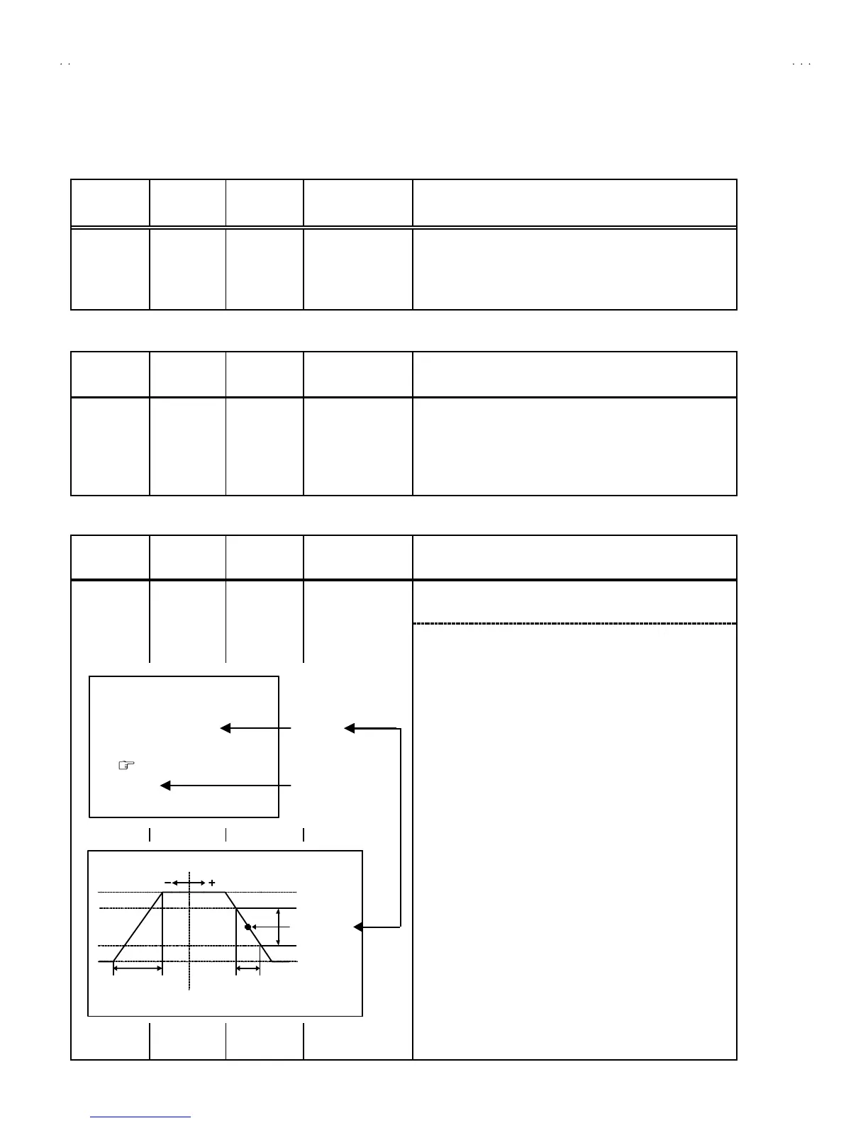
Ad just ment
of VCO
Signal
generator
Remote
control unit
1. VCO
1. Input th e PA L f ull colour b ar (210 .25MHz) sig nal.
2. En ter th e SERVICE MENU.
3. Sele ct 1.IF f rom the SERVICE MENU.
4. Press 1 key and s elect 1. VCO.
5. Select VCO ADJ US T with MENU
▲
/
▼
key.
6. Press MENU -/+ key until the colour of the characters TOO
HIGH ch an ges b lu e to ye llow. Th en g r ad ually press th e MENU
-/+ key u ntil th e TOO LOW ch ang es yellow. At this t ime, conf irm
th at t he valu e of VCO ADJUST is n ear +00 .
0. Select AFT ADJUST with MENU ▲/▼ key.
8. Press MENU -/ + key until the characters JUST REFERENCE
ch ang es b lue to yellow.
9. Press the DI SPLAY key three times to return to normal screen.
VCO (C W)
***.**
MHz
TOO HIGH
AB OVE REFEREN CE
JU ST REF ER ENCE
BELOW R EFEREN CE
TOO LOW
AFT AD JUST
** *(* *)
** *(* *)** *(* *)
** *(* *)
VCO ADJUST
** *(* *)
** *(* *)** *(* *)
** *(* *)
FINE
DISP : EXIT
YE LLOW
D
 Loading...