No. 51669
V-A14M3
V-A14T3
V-A14AU3
V-1413EE
25
Item
Measuring
instrument
Test point Adjustment part Description
Adjustment
of VER. LIN.
& VER.
SCURVE
z
Remote
control
unit
4. VER. LIN.
5. VER. SCURVE
x
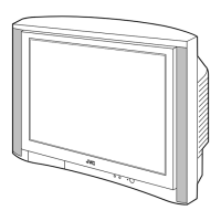
When the vertical linearity is too bad, Perform the following steps.
13. Receive a cross-hatch signal.
14. Select
4. VER. LIN.
with the MENU
▲
/
▼
key.
15. Set the initial setting value of
4. VER. LIN.
with the MENU - / +
key.
16. Select
5. VER. SCURVE
with the MENU
▲
/
▼
key.
17. Set the initial setting value of
5. VER. SCURVE
with the
MENU - / + key.
18. Adjust
4. VER. LIN.
and
5. VER. SCURVE
so that the spaces
of each line as shown in Fig.3 on
TOP
,
CENTER
and
BOTTOM
become uniform.
19. Make sure that the adjustment is properly done on the screen
of 60Hz mode.
[NOTE]
z
Adjust to make both 50Hz & 60Hz are the same v. size and
fine straight line.
z
When adjust again, adjust 50Hz mode first.
z
When adjust in 60Hz mode, only 60Hz mode is adjust.
z
Ver, linearity adjustment is only time adjustment.
VSM PRESET ADJUSTMENT
Item
Measuring
instrument
Test point Adjustment part Description
Setting of
VSM
PRESET
z
Remote
control
unit
TINT
COLOUR
BRIGHT
CONT.
SHARP
(VSM PRESET)
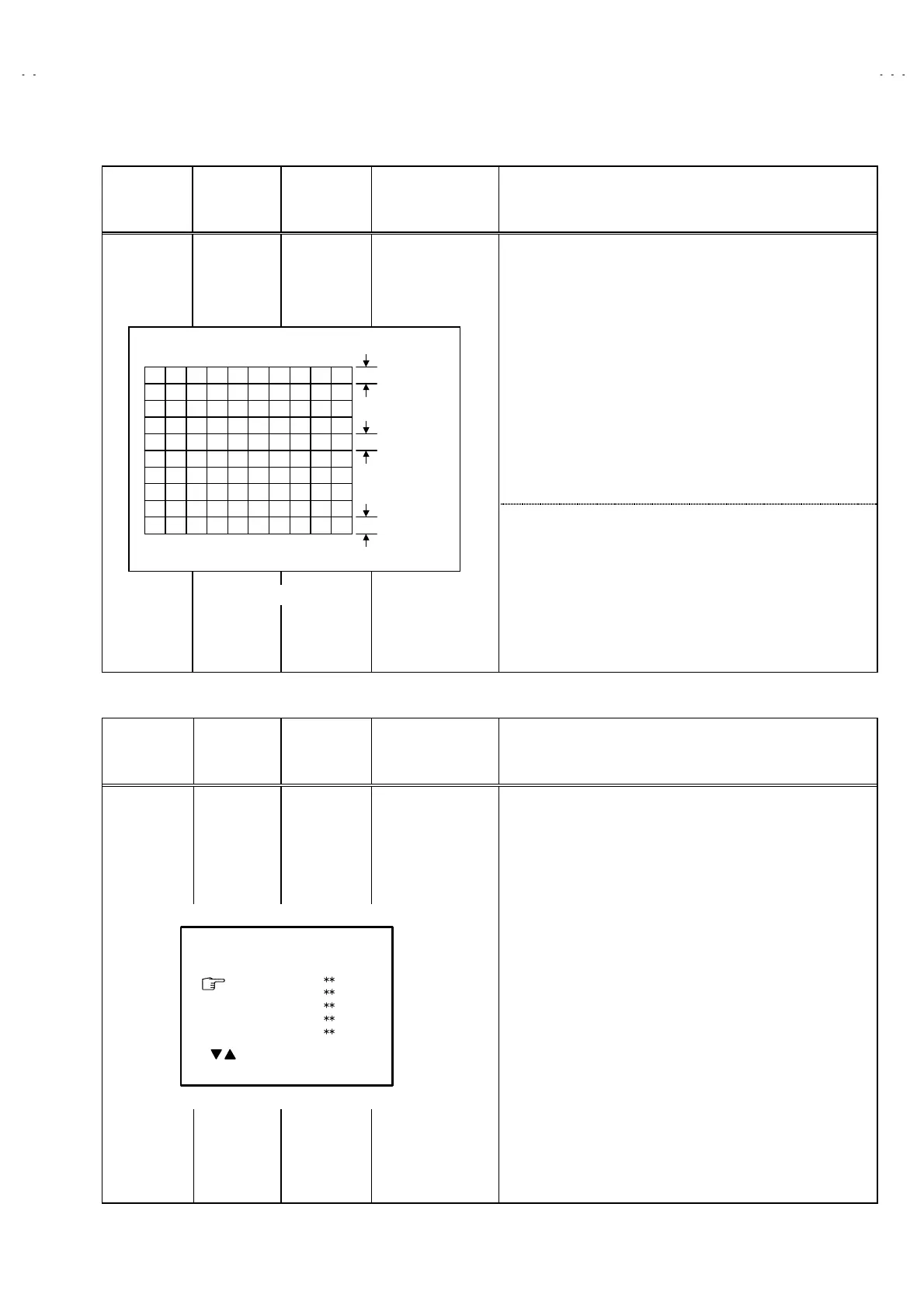
1. Select
4. VSM PRESET
from the SERVICE MENU.
2. Select BRIGHT with the PICTURE MODE key.
3. Adjust the MENU
▲
/
▼
and MENU - or + key to bring the set
values of
TINT
~
~~
~
SHARP
to the values shown in the table.
4. Respectively select the VSM PRESET mode for SOFT and
STANDARD, and make similar adjustment as in 3. above.
BRIGHT
TINT
COLOUR
BRIGHT
CONT.
SHARP
- / + : OPERATE DISP : EXIT
*
*
*
*
*
*
*
*
*
*
/ :SELECT
Fig.3
TOP
CENTER
BOTTOM
 Loading...