1-8 (No.MB736<Rev.003>)
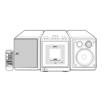
3.1.3 Removing the SMPS board (See Fig.5, 6)
(1) Disconnect the connector wire from Display board connect-
ed to connector CN902
of the SMPS board. (See Fig.5)
Fig.5
(2) Remove the two screws G, one screw H and one screw J
attaching the SMPS board. (See Fig.6)
Fig.6
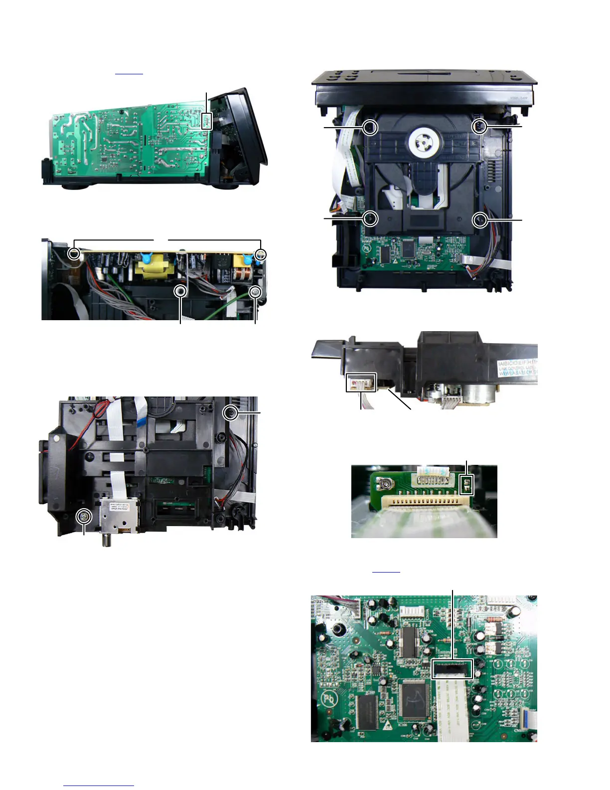
3.1.4 Removing the CD mechanism (See Fig.7, 8, 9, 10, 11)
(1) Remove the one screw K and one screw L attaching the
Rear cabinet bracket. (See Fig.7)
Fig.7
(2) Remove the two screws M and two screws N attaching the
CD mechanism. (See Fig.8)
Fig.8
(3) Disconnect the connector wire from MPEG board connect-
ed to connector of Loader board. (See Fig.9)
Fig.9
(4) Solder the short part of the Pickup board. (See fig.10)
Fig.10
(5) Disconnect the card wire from CD mechanism connected
to connector CN102
of the MPEG board. (See Fig.11)
Fig.11
CN902
G
HJ
K
L
M
N
M
N
Loader boardconnector
solder short part
CN102
 Loading...