(No.49787B)1-13
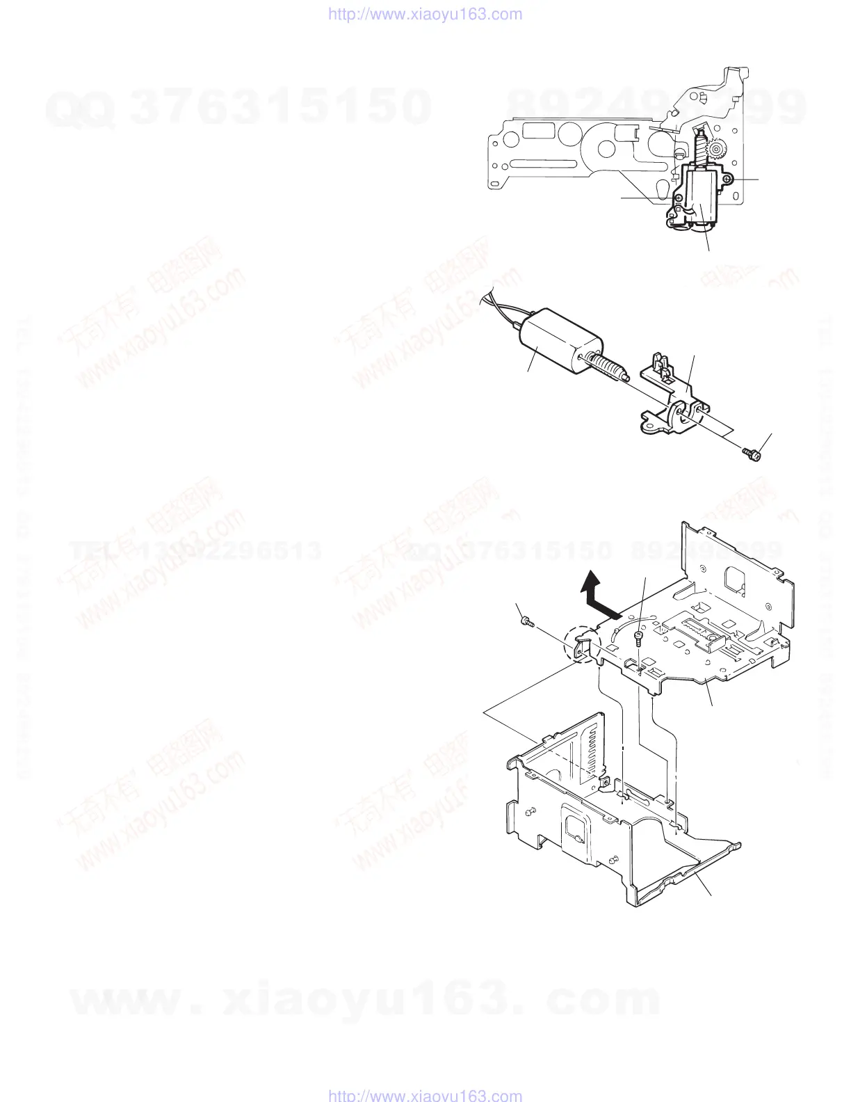
3.2.11 Tray motor
(See Fig.16 and 17 )
(1) Remove the two screws S securing the tray motor.
(2) Remove the two screws T to remove the tray motor as-
sembly from the tray motor holder.
Fig.16
Fig.17
3.2.12 Separation of the chassis (L) assembly and chassis (R) assembly
(See Fig.18 )
(1) Remove the two screws U retaining the chassis (L) and (R)
assemblies.
(2) Slide the chassis (L) assembly toward the front and detach
it, then remove the chassis (L) upward.
Fig.18
Tray motor assembly
S
S
Tray motor
Tray motor holder
T
Front side
U
U
Slide and remove upward
as shown by the arrow
Chassis (L) assembly
Chassis (R) assembly
w
w
w
.
x
i
a
o
y
u
1
6
3
.
c
o
m
Q
Q
3
7
6
3
1
5
1
5
0
9
9
2
8
9
4
2
9
8
T
E
L
1
3
9
4
2
2
9
6
5
1
3
9
9
2
8
9
4
2
9
8
0
5
1
5
1
3
6
7
3
Q
Q
TEL 13942296513 QQ 376315150 892498299
TEL 13942296513 QQ 376315150 892498299
http://www.xiaoyu163.com
http://www.xiaoyu163.com
 Loading...