DR-E34BK
DR
-E34LBK
(3)
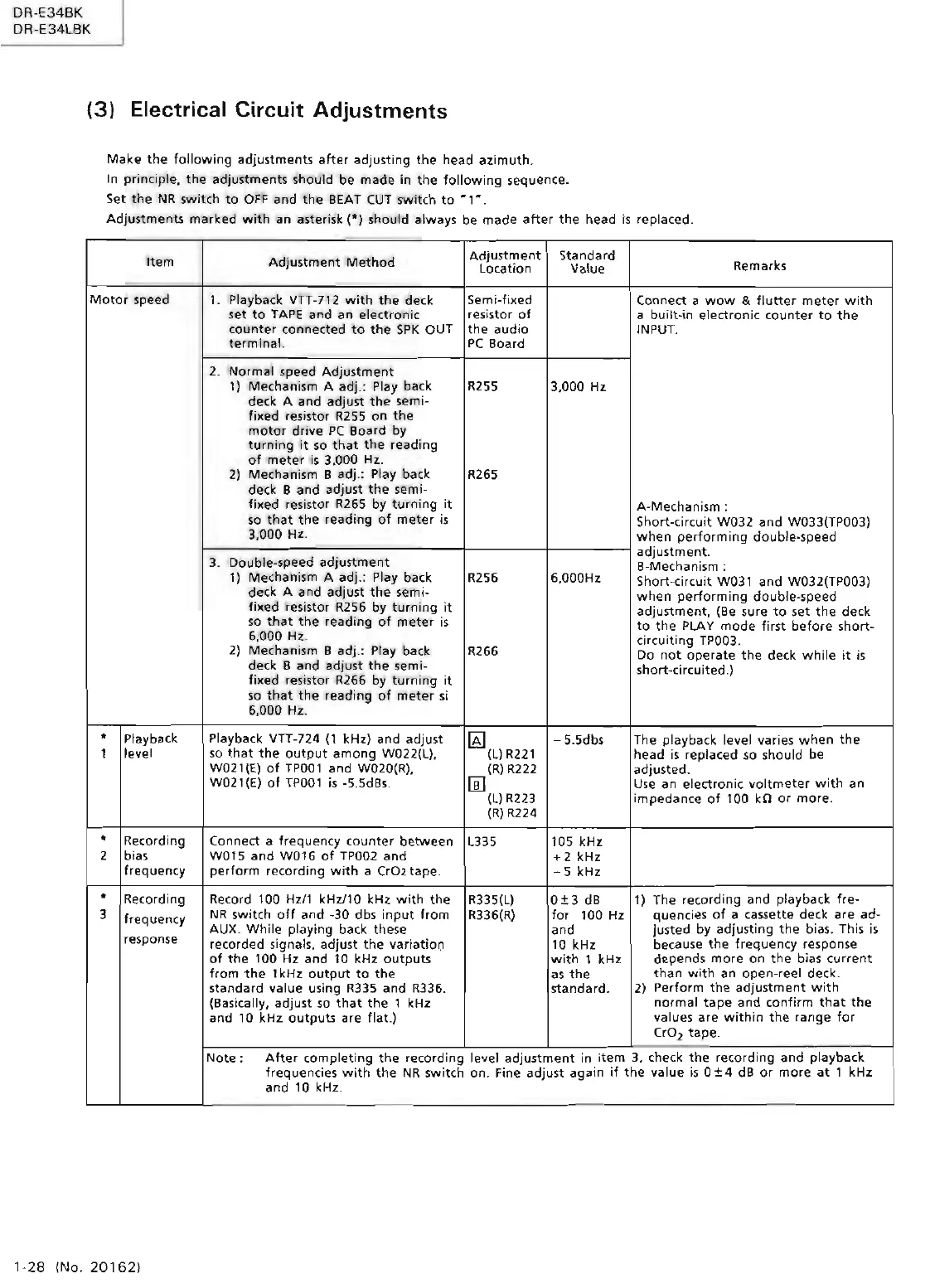
Electrical Circuit Adjustments
Make
the
following
adjustments
after
adjusting
the
head
azimuth.
In
principle,
the
adjustments should be
made
in the
following
sequence.
Set
the
NR
switch
to
OFF
and
the
BEAT
CUT
switch
to
~
1 " .
Adjustments
marked
with
an
asterisk(*)
should always be
made
after
the
head
is
replaced.
Item
Adjustment
Method
Adjustment
Standard
Remarks
Location Value
Motor
speed
1.
Playb,1ck VTT-712
with
the
deck
Semi-fixed
Connect a
wow
& fl
utter
meter
with
set
to
TAPE
and
an
electronic resistor
of
a
built-in
electronic
counter
to
the
counter
connected
to
the
SPK
OUT
the
audio
INPUT.
terminal.
PC
Board
2.
Normal
speed
Adjustment
1) Mechanism A
adj.:
Play back
R255
3,000
Hz
deck A and adjust
the
semi-
fixed res
istor
R255
on
the
motor
drive
PC
Board by
turning
it
so
that
the
reading
of
meter
is
3.000 Hz.
2)
Mechanism B adj.: Play back R265
deck B
and
adjust
the
semi-
fo<ed
resistor R265 by
turning
it
A-Mechanism :
so
that
the
reading
of
meter
is
Short-circuit W032
and
W033(TP003)
3,000 Hz.
when
performing
double-speed
3.
Double-speed
adjustment
adjustment.
B-Mechanism :
1) Mechanism A adj.: Play back
R256 6,000Hz
Short-circuit W031
and
W032(TP003)
deck A and adjust
the
semi-
when
performing
double-speed
fixed resistor R256 by
turning
it
adjustment, (Be sure
to
set
the
deck
so
that
the
reading
of
meter
is
to
the
PLAY
mode
first
before
short-
6,000
Hz.
circuiting TP003.
2)
Mechanism B adj.: Play back
R266
Do
not
operate
the
deck
whi
le
it
is
deck B and adjust
the
semi-
short
-circuited.)
fixed
resistor R266 by
turning
it
so
that
the
reading
of
meter
si
6,000 Hz.
• Playback Playback VTT-724
(1
kHz) and
adjust
gJ
-5
.Sdbs The playback level
var
i
es
when
the
l
level
so
that
the
output
among
W022(L).
(L)
R221
head is replaced so should be
W021(E)
of
TP001
and W020(R),
(R)
R222
adjusted.
W021
(El
of
TP001
is
-5.SdBs.
[ill
Use
an
electronic
voltmeter
with
an
(L)
R223
impedance
of
100
kfl
or
more.
(R)
R224
•
Recording Connect a frequency
counter
between
L3
35
105 kHz
2 bias
WO
15
and
W016
of
TP002
and
+ 2 kHz
frequency
perform
recordi
ng
with
a Cr02 tape.
-5
kHz
•
Recording
Record 100 Hzl1 kHz/10 kHz
with
the
R335(L)
0±3
dB
1)
The recording
and
playback
fre-
3
frequency
NR
switch
off
and
-30 dbs
input
from
R336(R)
for
100 Hz
quencies
of
a cassette deck
are ad-
AUX.
While
playing back these
and
justed by adjusting
the
bias. This is
response
recorded signals. adjust
the
variatioo
10 kHz because
the
frequency response
of
the
100 Hz and 10 kHz
outputs
with
1 kHz depends
more
on
the bias cur
rent
from
the
1 kHz
output
to
the
as
the
than
with
an
open-reel deck.
standard value using R335
and
R336.
standard.
2)
Perform
the
ad
j
ustment
w i
th
(Basically, adjust
so
that
the
1 kHz
norma
l
tape
and
confirm
that
the
and 10 kHz
outputs
are
flat.)
values
are
with
in
the
r
ange
for
Cr0
2
tape
.
Note:
After
completing
the
recording level
adjustment
in
item
3, che
ck
the
recor
ding
and
playback
frequencies
with
the
NR
switch
on.
Fine adjust again
if
the
value
is
O ± 4
dB
or
more
at
1 kHz
and
1 O kHz.
1-28
(No.
20162)