Do you have a question about the JVC DR-E34BK and is the answer not in the manual?
Critical safety instructions, warnings, and precautions for handling the equipment.
Circuit diagram for the tuner section, part one.
Layout diagram of the Tuner PC Board (ENA-094).
Block diagram illustrating system control and audio signal flow.
Diagram showing external connections for the receiver.
Instructions for installing AM loop and external antennas.
Instructions for connecting FM antennas, including coaxial and feeder types.
Details for connecting 75-ohm and 300-ohm FM antennas.
Guidance on connecting cords and using the Beat Cut function.
Instructions for using the 10-key pad for tuning and CD selection.
Guidelines for operating the remote control with the main unit.
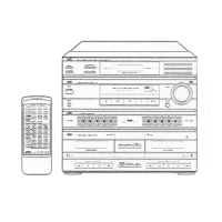
Explanation of tuner section controls and indicators.
Details on amplifier controls, indicators, and features.
Overview of input source selection and status indicators.
Function of the remote sensor and status indicator lights.
Explanation of volume and balance adjustment controls.
Description of the Sound Effect Amplifier graphic equalizer.
Overview of cassette deck controls, indicators, and features.
Selecting AM channel spacing based on regional requirements.
Step-by-step guide for powering on, selecting sources, and adjusting audio.
Methods for tuning AM/FM broadcasts: manual, auto, preset, and scan.
Procedure for storing and recalling preset radio stations.
Instructions for loading and playing cassette tapes, including Dolby NR.
Controls for tape playback: pause, stop, continuous play, auto-reverse.
Steps for recording audio onto cassette tape, including pause and stop.
Using the S.E.A. graphic equalizer for recording operations.
Instructions for normal and high-speed dubbing tapes between decks.
Procedure for directly recording a CD onto cassette tape.
Edit recording, mute intervals, and erasing cassette tapes.
Tape types, safety features, and instructions for playing records.
Procedure for cleaning cassette heads for optimal performance.
Cleaning pinch rollers, capstans, and demagnetizing tape heads.
Technical details for the amplifier section.
Technical details for FM and AM tuner sections.
Technical details for the cassette deck section.
Power consumption, dimensions, weight, and general specs.
Steps for removing the top cover and front panel assembly.
Procedures for removing the cassette mechanism and door.
Steps for removing PC boards and controls like master volume.
Detailed explanation of the system control IC, HD614081SB47.
Description of the LC6514B-4245 tuner controller IC.
IC terminal layout, key matrix, and detailed pin functions.
Terminal layout and key matrix for the deck system controller IC.
Detailed description of each pin's function for the deck controller IC.
Key functions of the LA3401 FM MPX detector IC.
Visual representation of the IC's top view and internal block diagram.
Detailed explanation of each pin's function for the LA3401 IC.
Key functions of the LA1266A FM AM IF amplifier and detector IC.
Visual representation of the IC's top view and its block diagram.
Detailed explanation of each pin's function for the LA1266A IC.
Key functions of the LC7218 PLL synthesizer IC.
IC terminal layout, block diagram, and detailed pin function descriptions.
Description of the TC9163N analog switch IC.
Description of the GP1U501X remote control module IC.
Description of the HA12136A noise reduction amplifier IC.
Description of the μPC1237HA protector IC.
Description of the LB1639-CV motor driver IC.
Layout, pin connections, and anode table for the FL display tube.
List of necessary measuring instruments for cassette deck adjustments.
Procedures for adjusting and repairing cassette deck mechanisms.
Procedure for setting the recording level for optimal audio quality.
Methods for checking recording distortion and signal-to-noise ratio.
Procedures for checking erase ratio and auto-stop functionality.
Procedures for adjusting motor speed for normal and double speeds.
Adjusting playback level and recording bias frequency.
Procedure for adjusting the recording frequency response.
Alignment steps for the tuner's front-end section.
Alignment of the tuner's IF, detection, and multiplex sections.
Alignment procedures for the LW tuner section, including antenna coil.
Alignment procedures for the MW tuner section, including antenna coil.
Overall exploded view and comprehensive parts list.
List of parts for the cassette mechanism assembly.
Parts lists for various printed circuit boards (ENJ, ENC, ENA, ENB).
List of included accessories with the unit.
Details on packing materials and corresponding part numbers.
Key to understand regional designations for parts listed.
Detailed parts list for the A mechanism of the cassette deck.
Detailed parts list for the B mechanism of the cassette deck.
List of integrated circuits used on the ENC-073 board.
List of transistors used on the ENC-073 board.
List of diodes used on the ENC-073 board.
List of capacitors used on the ENC-073 board.
List of integrated circuits used on the ENA-099 board.
List of transistors used on the ENA-099 board.
List of diodes used on the ENA-099 board.
List of capacitors used on the ENA-099 board.
List of resistors used on the ENA-099 board.
List of other components used on the ENA-099 board.
List of integrated circuits used on the ENA-094 board.
List of transistors used on the ENA-094 board.
List of diodes used on the ENA-094 board.
List of capacitors used on the ENA-094 board.
List of resistors used on the ENA-094 board.
List of other components used on the ENA-094 board.
List of diodes used on the ENB-101 board.
List of other components used on the ENB-101 board.
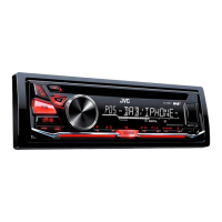
| Type | Car Receiver |
|---|---|
| Model | DR-E34BK |
| Brand | JVC |
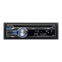
| Tuner | AM/FM |
| Audio Formats | MP3, WMA |
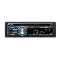
| Output Power | 50W x 4 |
| RMS Power Output | 22W x 4 |
| Preamp Voltage | 2.5V |
| Bluetooth | No |
| USB Port | Yes |
| Aux Input | Yes |
| Display | LCD |
| DIN Size | Single DIN |
| Detachable Face | Yes |
| Number of Channels | 4 |
| ID3 Tag Display | Yes |
| Number of AM Presets | 12 |
| Number of FM Presets | 18 |
| Remote Control | Yes |
| Disc Playback | CD |