3
SPECIFICATIONS
KS-AX3204 KS-AX3202 KS-AX3201D
Power Output
• Normal Mode:
Signal-to-Noise Ratio
60 W RMS × 4 channels at 4 Ω and ≤ 1% THD + N
76 dBA (reference: 1 W into 4 Ω)
65 W RMS × 2 channels at 4 Ω and ≤ 1% THD + N
76 dBA (reference: 1 W into 4 Ω)
250 W RMS × 1 channels at 4 Ω and ≤ 1% THD + N
60 dBA (reference: 1 W into 4 Ω)
Power Output
• Normal Mode:
90 W RMS × 4 channels at 2 Ω and ≤ 1% THD + N 90 W RMS × 2 channels at 2 Ω and ≤ 1% THD + N 400 W RMS × 1 channels at 2 Ω and ≤ 1% THD + N
• Bridge Mode:
150 W RMS × 2 channels at 4 Ω and ≤ 1% THD + N 150 W RMS × 1 channels at 4 Ω and ≤ 1% THD + N
—
Maximum Power Output 800 W (400 W × 2) 400 W 800 W
Load Impedance
• Normal Mode:
4 Ω (2 Ω to 8 Ω allowance) 4 Ω (2 Ω to 8 Ω allowance) 4 Ω (2 Ω to 8 Ω allowance)
• Bridge Mode:
4 Ω (4 Ω to 8 Ω allowance) 4 Ω (4 Ω to 8 Ω allowance)
—
Frequency Response 5 Hz to 50,000 Hz ( +0 dB, –3 dB) 5 Hz to 50,000 Hz ( +0 dB, –3 dB) 20 Hz to 200 Hz ( +0 dB, –3 dB)
Input Sensitivity/Impedance
2 V/21 kΩ (0.3 V to 6 V, variable) 2 V/21 kΩ (0.3 V to 6 V, variable) 2 V/40 kΩ (0.3 V to 6 V, variable)
Distortion Less than 0.04% (at 1 kHz) Less than 0.04% (at 1 kHz) Less than 0.08% (at 100 Hz)
Power Requirement DC 14.4 V (11 V to 16 V allowance) DC 14.4 V (11 V to 16 V allowance) DC 14.4 V (11 V to 16 V allowance)
Grounding system Negative ground Negative ground Negative ground
Dimensions (W×H×D) 340 mm × 53.5 mm × 185 mm
(13-
7
/16 in. × 2-
1
/8 in. × 7-
5
/16 in.)
207 mm × 53.5 mm × 185 mm
(8-
3
/16 in. × 2-
1
/8 in. × 7-
5
/16 in.)
227 mm × 53.5 mm × 185 mm
(8-
15
/16 in. × 2-
1
/8 in. × 7-
5
/16 in.)
Mass (approx.) 2.3 kg (5.1 lbs) 1.48 kg (3.4 lbs) 1.77 kg (4.0 lbs)
Accessories Speaker input connector 3P × 2
Mounting Screw
φ
4 × 20 mm (13/16 in.) × 4
Speaker input connector 3P × 1
Mounting Screw
φ
4 × 20 mm (13/16 in.) × 4
Speaker input connector 3P × 1
Mounting Screw
φ
4 × 20 mm (13/16 in.) × 4
Designandspecicationsaresubjecttochangewithoutnotice.
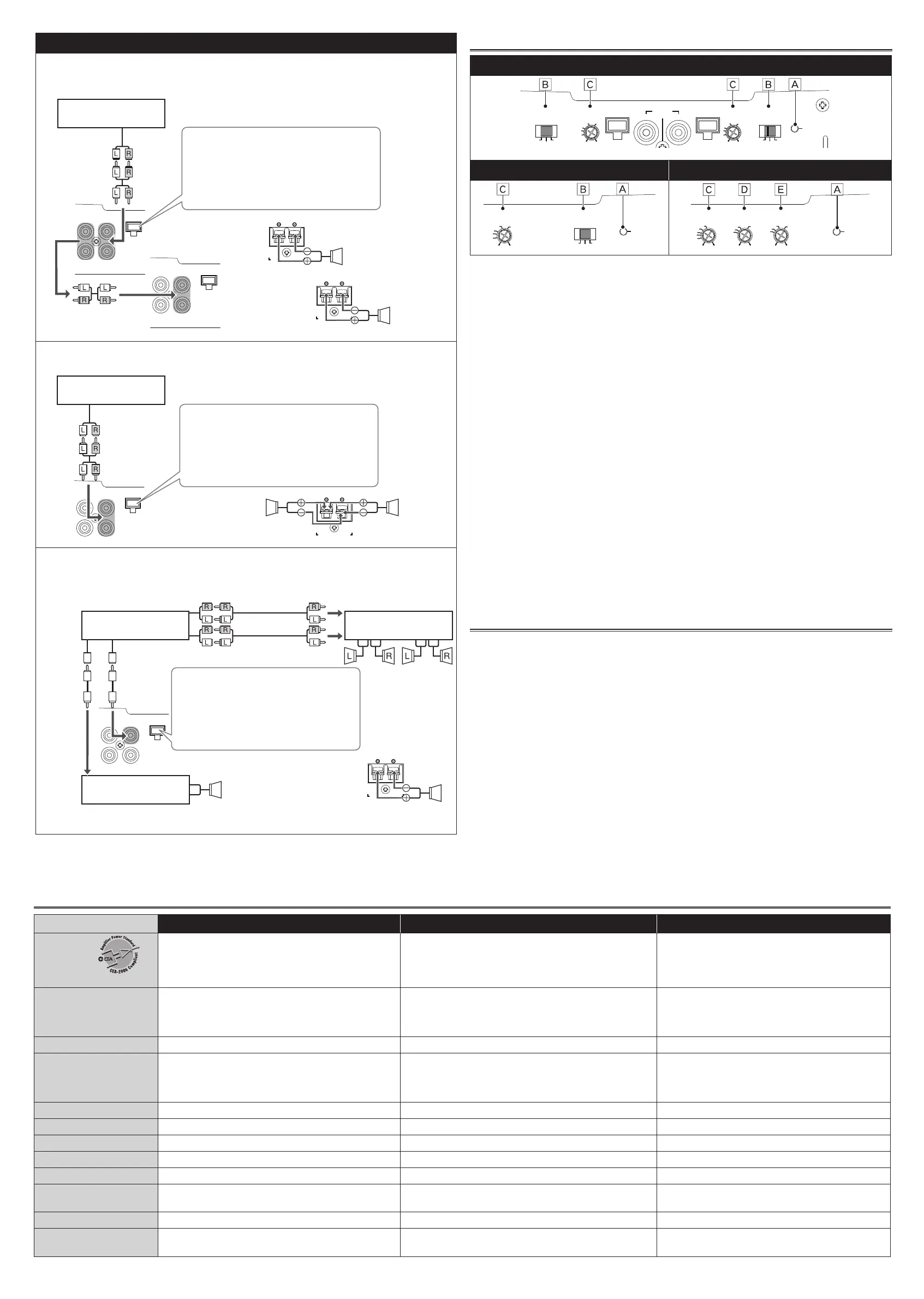
CONTROLS
KS-AX3204
CROSSOVER
HIGH
INPUT
INPUT SENS.
LPF HPF
OFF
L
/
MONO L
/
MONO
INPUT
HIGH
INPUT
INPUT SENS.
CROSSOVER
POWER
HPFLPF
OFF
0
.
2V5V
0
.
5
1
2
4
3
0
.
5
1
4
3
2
0
.
2V5V
FRONT REAR
KS-AX3202 KS-AX3201D
CROSSOVER
LPF
HPF
POWER
INPUT SENS.
0
.
5
1
4
3
2
INPUT SENS.
LPF
BASS BOOST
POWER
200Hz
150
50Hz
70
10
120
18dB
2
0
.
2V5V 0dB
3
5
1
8
0
.
5
1
3
2
4
0
Å POWER indicator
The green lamp lights while the unit is turned on.
ıCROSSOVERfilterswitch
OFF: Normally set to this position. The switch is preset to this position when the unit is
shipped.
LPF:SettothispositionwhenyouwanttoturnontheLPF(Low-PassFilter)switch.TheLow-
PassFiltertransmitsfrequencieslowerthan80Hz.
HPF:SettothispositionwhenyouwanttoturnontheHPF(High-PassFilter)switch.The
High-PassFiltertransmitsfrequencieshigherthan150Hz.
ÇINPUTSENS.(inputsensitivity)controller
Setthiscontrolaccordingtotheline-outputlevelofthecenterunitconnectedwiththisunit.
Fortheline-outputlevel,refertothe<Specications>intheinstructionmanualofthecenter
unit.
If the line-output level of the center unit is unknown, set it in the following procedure:
1.TurntheInputsensitivitycontrolto"5"(minimum).
2. Play a CD source.
3.Increasethevolumeofthecenterunitgraduallytothemaximumlevelatwhichsoundisnot
distorted.
4.TurntheInputsensitivitycontrolclockwisetoalevelslightlybelowthelevelatwhichsound
startstobedistorted.
This controller is preset to 5V when the unit is shipped.
ÎBASSBOOSTcontroller
Turningthisbooststhe45Hzfrequencywithintherangeof0dBto+18dB.Adjustthelevel
while listening to the sound. This controller is preset to MIN when the unit is shipped.
‰LPF(Low-PassFilter)controller
Adjustthecutofffrequency(theLow-PassFiltertransmitsfrequencieslowerthanthecutoff
frequency)withintherangeof50Hzto200Hz.Adjustthelevelwhilelisteningtothe
sound.Thiscontrollerispresetto50Hzwhentheunitisshipped.
TROUBLESHOOTING
The POWER indicator does not light.
•Changethefusesifthecurrentoneisblown.
•Connectthegroundleadsecurelytoametalpartofthecar.
•Turnontheequipmentconnectedtothisunit.
•Confirmthebatteryvoltage(11Vto16V).
•Usearelayifyoursystememploystoomanyamplifiers.
•Leavetheunitturnedofftocoolitdownifitheatsupabnormally.
No sound is heard.
•Confirmtheconnectionsforthepowersupply(see"POWERSUPPLY"onpage1).
•ConnecttheRCApincordstotheINPUTjacks,orthespeakerinputconnectortotheHIGH
INPUT terminal.
•ConfirmthespeakerwiringsandthepositionoftheCROSSOVERfilterswitch(See“SPEAKER
CONNECTIONS”onpage2).
Alternator noise is heard.
•KeeptheleadsofthePOWERterminalsawayfromtheRCApincords.
•KeeptheRCApincordsawayfromotherelectricalcablesinthecar.
•Connectthegroundleadsecurelytoametalpartofthecar.
•Makesurethespeakernegativeleadsdonottouchthecarchassis.
•Connectabypasscapacitoracrosstheaccessoryswitches(horn,fan,etc....).
Noise is made when you connect the unit to an AM (MW/LW) tuner.
•Movealltheleadsofthisunitawayfromtheantenna(aerial)lead.
KS-AX3201D
2-Subwoofer system (2 amplifiers)
•Usethespeakerswithanimpedanceof2Ωto8Ω.
•IncomingsignalsfromINPUTjacksareemittedthroughthePREOUTjacks.
SPEAKER OUTPUT
SPEAKER OUTPUT
L
/
MONO
HIGH
INPUT
PRE OUT INPUT
L
R R
L
/
MONO
HIGH
INPUT
PRE OUT INPUT
L
R R
Line out (Rear)
or
Subwoofer out
JVC car receiver, etc.
ı Speaker input connector.
Connector lead To Receiver
a White "LEFT (+)"
=
Left (+) lead
b Black "RECEIVER GND"
=
Chassis*
1
c Gray "RIGHT (+)"
=
Right (+) lead
Å
Subwoofer
*
2
Subwoofer
*
2
2-Subwoofer system
•Usethespeakerswithanimpedanceof4Ωto8Ω.
SPEAKER OUTPUT
L
/
MONO
HIGH
INPUT
PRE OUT INPUT
L
R R
Line out (Rear)
or
Subwoofer out
*
2
JVC car receiver, etc.
ı Speaker input connector.
Connector lead To Receiver
a White "LEFT (+)"
=
Left (+) lead
b Black "RECEIVER GND"
=
Chassis*
1
c Gray "RIGHT (+)"
=
Right (+) lead
Å
Subwoofer
Subwoofer
5-speaker system plus subwoofer—5.1-channel (3 amplifiers)
•Usethespeakerswithanimpedanceof2Ωto8Ω.
•Besuretoconnectthelineoutputfromthereceivertotheleft(L)jackonthisunit.
SPEAKER OUTPUT
L
/
MONO
HIGH
INPUT
PRE OUT INPUT
L
R R
JVC car receiver, etc.
ı Speaker input connector.
Connector lead To Receiver
a White "LEFT (+)"
=
Left (+) lead
b Black "RECEIVER GND"
=
Chassis*
1
c Gray "RIGHT (+)"
=
Left (+) lead
Å
Subwoofer
*
2
JVC amplifier, etc.
(Purchased separately)
JVC amplifier, etc.
(Purchased separately)
Center Speaker
Front
Speaker
Rear
Speaker
Line out (Front)
Line out (Rear)
*
2
*
2
*
2
Line out
(Center)
Subwoofer out
KSAX320_EN_GE_NL_FR_UK_PE.indd 3 12/11/22 12:04
 Loading...