(No.MB666<Rev.005>)1-11
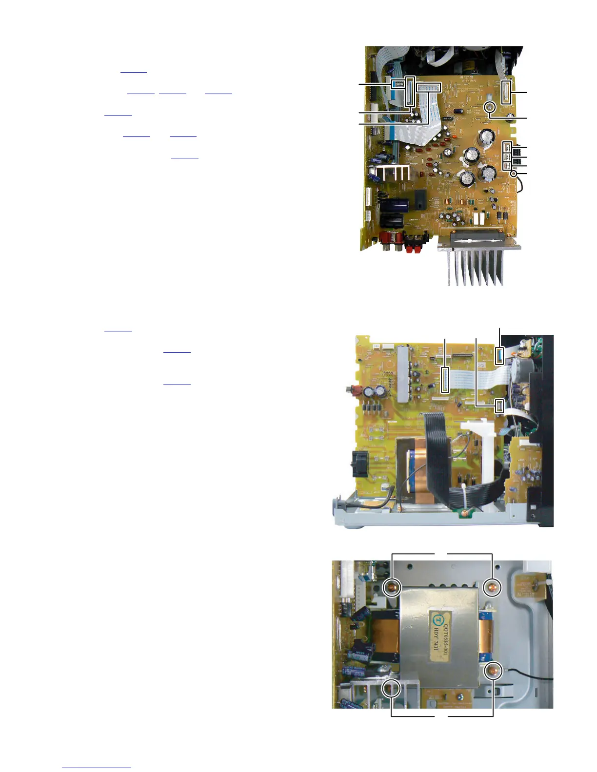
3.1.8 Removing the Amp board (See Fig.13)
(1) Disconnect the Earth wire from Bottom chassis connected
to post pin PP701
of the Amp board.
(2) Disconnect the flat cable wire from Micom board connected
to connector CN700
, CN701 and CN702 of the Amp board.
(3) Disconnect the card wire from Mic board connected to con-
nector CN750 of the Amp board.
(4) Disconnect the card wires from Micom board connected to
connectors CN705
and CN706 of the Amp board.
(5) Disconnect the flat cable wire from Headphone jack board
connected to connector CN760
of the Amp board.
(6) Remove the one screw M attaching the Amp board.
Fig.13
3.1.9 Removing the Micom board (See Fig.14, 15)
(1) Disconnect the card wire from FL board connected to con-
nector CN500
of the Micom board. (See Fig.14)
(2) Disconnect the card wire from Cassette mechanism A con-
nected to connector CN501 of the Micom board. (See
Fig.14)
(3) Disconnect the flat cable wire from PLAY button board con-
nected to connector CN430
of the Micom board. (See
Fig.14)
(4) Remove the four screws N attaching the Power transform-
er. (See Fig.15)
Fig.14
Fig.15
M
PP701
CN700
CN701
CN702
CN750
CN760
CN706
CN705
CN501
CN500
CN430
N
N
 Loading...