1-10 (No.MB666<Rev.005>)
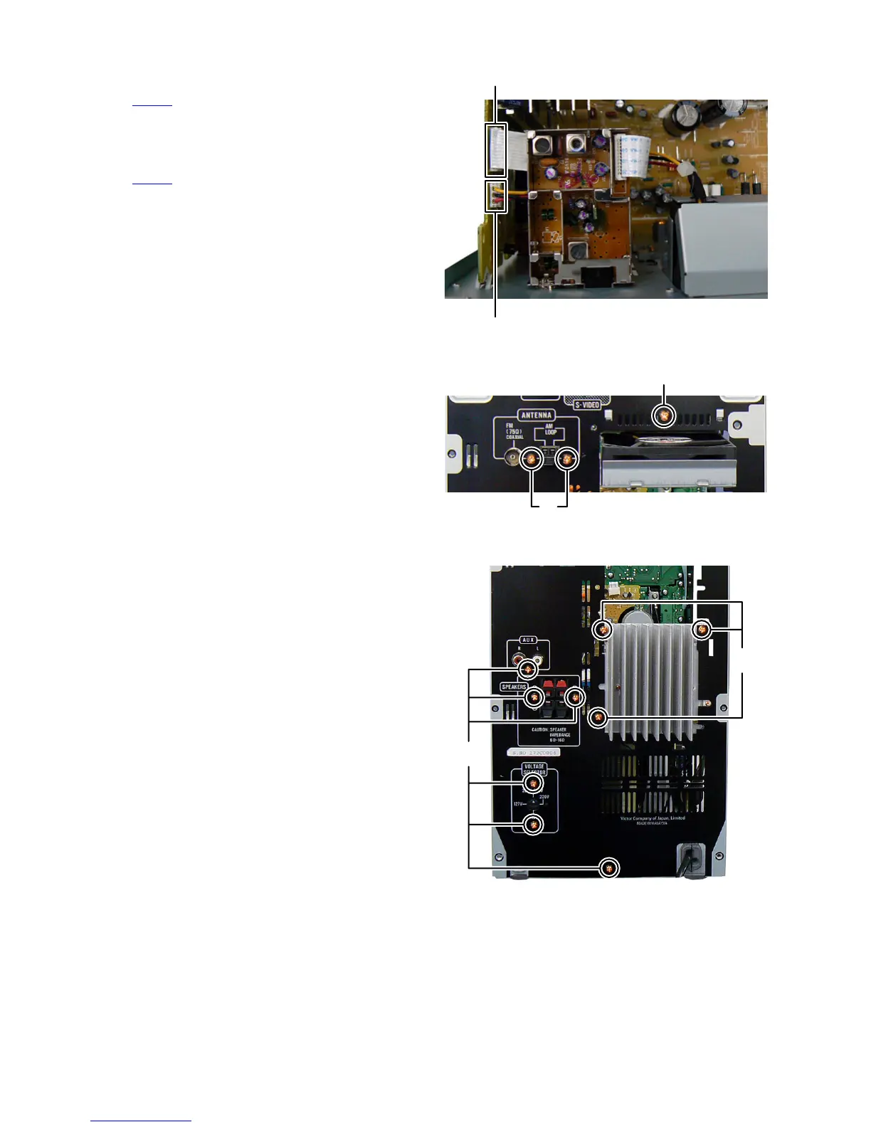
3.1.5 Removing the Fan (See Fig.10, 11)
(1) Disconnect the4 connector wire from Fan connected to
connector CN630
of the Micom board. (See Fig.10)
(2) Remove the one screw H attaching the Fan. (See Fig.11)
3.1.6 Removing the Tuner pack (See Fig.10, 11)
(1) Disconnect the card wire from Tuner pack connected to
connector CN507
of the Micom board. (See Fig.10)
(2) Remove the two screws J attaching the Tuner pack. (See
Fig.11)
Fig.10
Fig.11
3.1.7 Removing the Rear panel (See Fig.12)
(1) Remove the three screws K attaching the Heat sink.
(2) Remove the six screws L attaching the Rear panel.
Fig.12
CN507
CN630
H
J
L
K
 Loading...