1-14 (No.MB399)
3.1.7 Removing the digital amplifier board assembly
(See Figs.15 and 16)
• Remove the side panels L/R, top panel assembly, rear panel
and switching power supply.
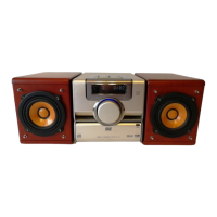
(1) From the top side of the main body, remove the screw Q
attaching the digital amplifier board assembly. (See
Fig.15.)
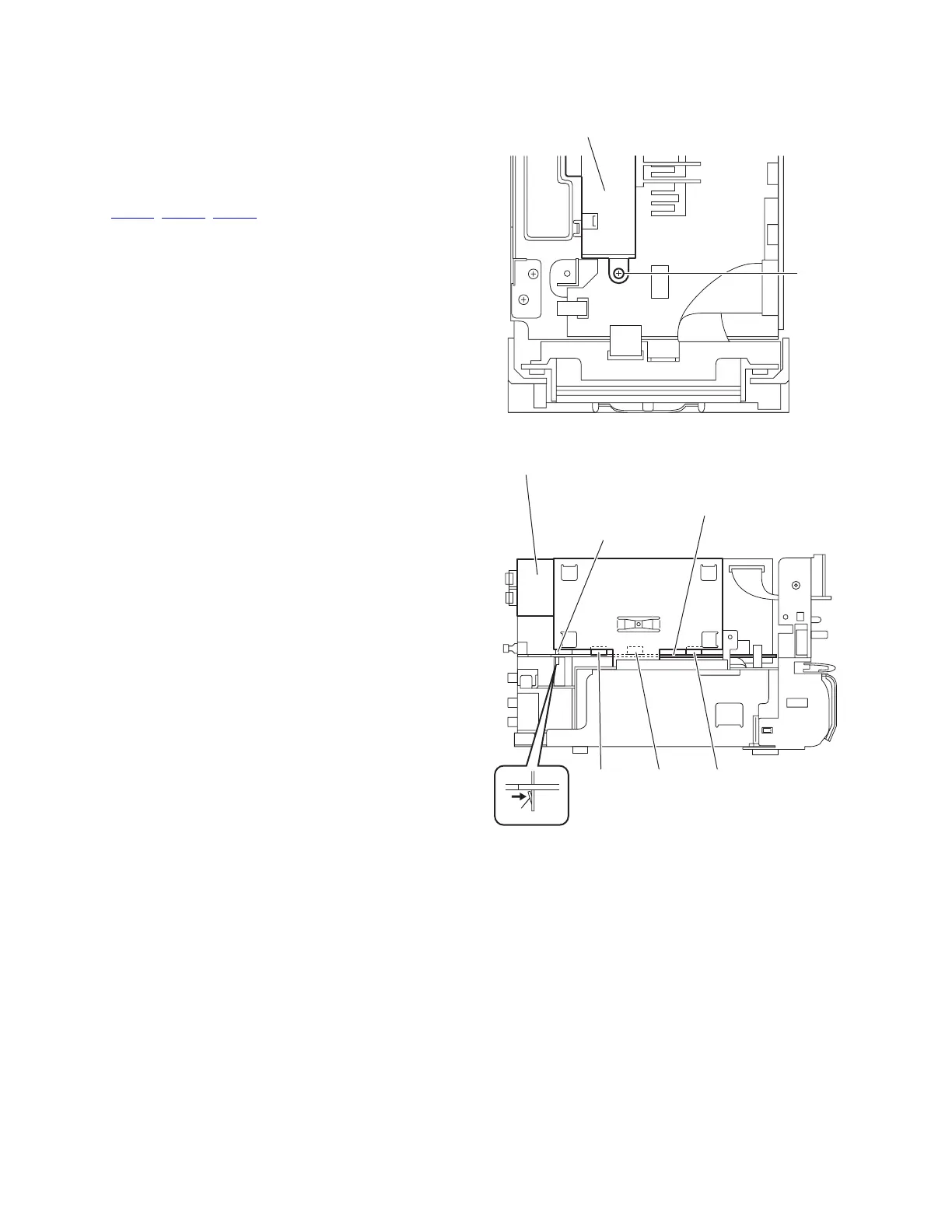
(2) From the left side of the main body, disconnect the connec-
tors (CN310
, CN311, CN312) on the digital amplifier board
assembly from the regulator board. (See Fig.16.)
(3) Release the joint g of the shield case B in the direction of
the arrow and take out the digital amplifier board assembly
from the main body. (See Fig.16.)
Fig.15
Fig.16
Digital amplifier board assembly
Q
Digital amplifier board assembly
Shield case B
CN312 CN311 CN310
Regulator board
g
 Loading...