2-3
UX-G6/FS-G6
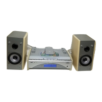
Removing the front sub panel assembly
(See Fig.6 to 8)
• Prior to performing the following procedure,
remove the top cover and the front panel assem-
bly.
1. Disconnect the card wire from connector CN704
on the back of the front sub panel assembly.
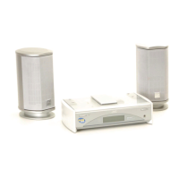
2. Remove the two screws D on the bottom of the
body.
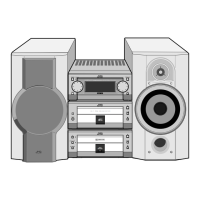
3. Release the joint "b" on the bottom and the two
joints "c" on both sides of the body, and remove
the front sub panel assembly toward the front.
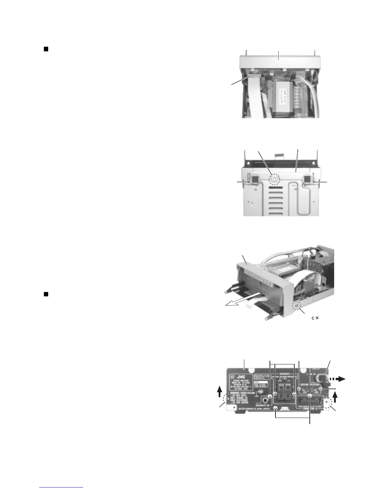
Removing the rear panel and the voltage
selector (See Fig.9)
• Prior to performing the following procedure,
remove the top cover.
1. Remove the cord stopper on the rear panel while
moving it in the direction of the arrow.
2. Remove the two screws E attaching the voltage
selector on the rear panel.
(The voltage selector can be removed without
removing the rear panel.)
3. Remove the five screws F attaching the rear
panel and release the two joints "d" on both sides
while moving the rear panel upward.
Fig. 6
Fig. 7
Fig. 8
Fig. 9
Front sub panel assembly
CN704
D
D
Joint b
Joint 2
F
F
E
E
Joint d
Joint d
Rear panel
Cord stopper
Front sub panel assembly
Front sub panel assembly
 Loading...