2-40
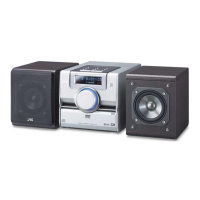
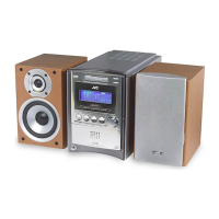
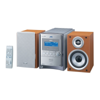
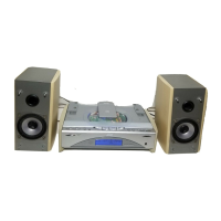
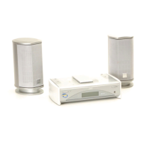
UX-G6/FS-G6
Procedures for adjusting the mechanism section
Caution for Changing the Head
Remove the screw provided from right above the head. At this time, peel the screw locks around the head by
using a sharp-pointed device. Moreover, use the screw driver matching the corresponding screw.
Adjustment of
head azimuth
Adjustment
of motor
speed
Confirmation
of wow flatter
Confirmation
of playing
torque
Forward
feeding/
reversing
torque
1. Connect the voltmeter to the
[LINE OUT] terminal.
2. Play the test tape VT705
(12.5kHz).
3. Adjust the head azimuth
screws so that the phase
difference between both the
forward and reverse channels
becomes maximum and the
output of both of the channels
becomes maximum.
1. Connect the frequency
counter to the [LINE OUT]
terminal.
2. Play the test tape VT712.
3. With VR671, adjust the
counter reading to 3,000Hz.
1. Connect the wow flatter meter
to the [LINE OUT] terminal.
2. Play the test tape VT712
(3kHz).
3. Confirm that the wow flatter
value is within 0.18%
(JIS WTD).
1. Confirm the playing torque by
using the torque test tape
(TW2131 [FWD]) or the
CTG-N gauge.
1. Confirm the forward feeding/
reversing torque by using the
gauge as mentioned above
or using the test tapes
(TW2231 [FWD]/TW2241
[REV]).
1
2
3
4
5
Forward
and
reverse
azimuth
screws
VR671
Maximum
output
(within -1dB)
3000 10Hz
0.18% or less
(JID WTD)
26~75 g/cm
70~170 g/cm
(both FF/REW)
Items Adjusting position Reference value Remarks
Adjusting
position
Adjusting
screw
Forward
azimuth
screw
Reverse
azimuth
screw
 Loading...