(No.MB355)1-9
3.1.3 Front panel assembly section
3.1.3.1 Removing the front panel assembly
(See Fig7 to 10)
• Prior to performing the following procedure, remove the side
panel (R)/(L) and the top panel.
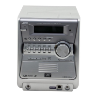
(1) From top of the body, disconnect the wire from connector
CN202
on the amp board.
(2) From rear left side of the body, disconnect the wire from
connector CN402
on the main board.
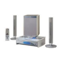
(3) From the bottom of the body, remove the screw F attaching
the front panel assembly.
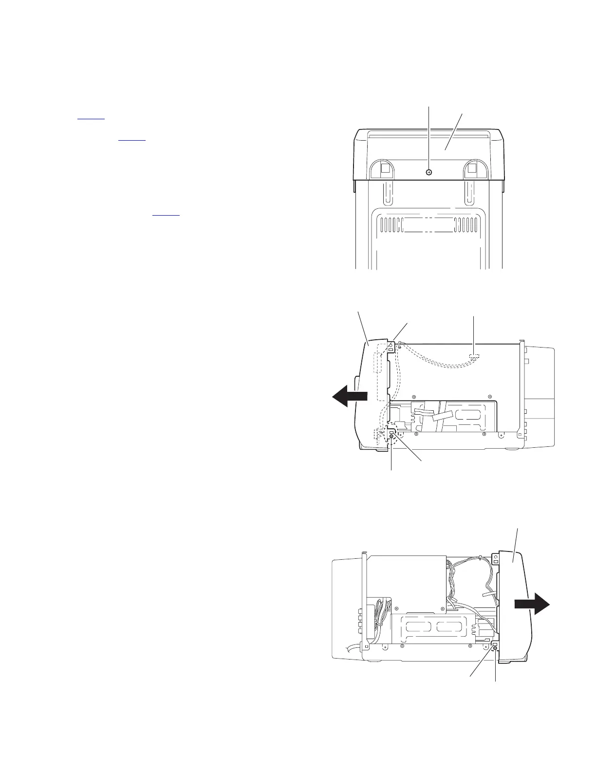
(4) From each side of the body, remove the two screws G at-
taching the front panel assembly.
(5) Release the two joints b on both lower sides of the body
and remove the front panel assembly forward while discon-
necting connector CN601
on the front side of the main
board.
Fig.8
Fig.9
Fig.10
Front panel assembly
F
Bottom
CN601
Main board
Front panel assembly
b
G
b
G
Front panel assembly
 Loading...