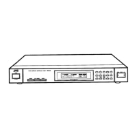
The JVC FX-335TN/FX-335LTN is an FM/AM Computer Controlled Tuner, designed for high-quality audio reception and integration into a larger audio system. This service manual provides comprehensive details on its functions, technical specifications, usage, and maintenance.
Function Description:
The primary function of the FX-335TN/FX-335LTN is to receive FM and AM (MW/LW) radio broadcasts. It features a computer-controlled tuning system, allowing for precise and stable reception. The tuner can be integrated into a JVC COMPU LINK Control System, enabling one-touch selection and synchronized operation with other JVC audio components. This system allows for automatic source selection and control of various A/V system functions from any desired source or a handheld remote control unit.
The tuner offers both manual and automatic tuning modes. In manual tuning, frequencies can be adjusted in steps of 50 kHz or 100 kHz for FM, 9 kHz or 10 kHz for AM (MW), and 1 kHz for AM (LW), depending on the model and region. Auto tuning allows the tuner to scan frequencies and stop when a broadcast is received. For weak or noisy FM stereo broadcasts, the FM MODE/MUTE function can be switched to "MONO" and "OFF" (mute off) to improve clarity, though the reception will be in mono.
Preset memory is a key feature, allowing up to 40 FM or AM stations to be stored. These presets can be recalled using a numeric keypad. The tuner also includes an "AUTO MEMORY" function, which automatically scans and stores broadcast frequencies into available preset channels. Unwanted preset channels can be canceled, and these canceled channels will be skipped during preset scanning.
The device includes various indicators on its front panel display:
- FM MODE indicator: Shows "AUTO" or "MONO" mode.
- FM MUTE indicator: Shows "ON" or "OFF" for muting.
- TUNED indicator: Lights when a broadcast is correctly received.
- STEREO indicator: Lights for FM stereo broadcasts (unless in MONO mode).
- FM/AM indicator: Displays "FM" or "AM" depending on the band.
- Frequency indicator: Shows frequency in MHz for FM and kHz for AM.
- MEMORY indicator: Lights for 5 seconds when the MEMORY button is pressed, or blinks for 5 seconds when AUTO MEMORY is pressed.
- CANCEL indicator: Lights for 5 seconds when the CANCEL button is pressed.
- PRESET STATION indicator: Displays the channel number of the selected preset station.
Important Technical Specifications:
FM Tuner:
- Tuning Range: 87.5 ~ 108.0 MHz (IHF/DIN)
- Usable Sensitivity: 10.8 dBf (0.95 µV/75 ohms)
- 26 dB Quieting Sensitivity (Mono): 1.0 µV/75 ohms
- 50 dB Quieting Sensitivity (Mono): 16.3 dBf (1.8 µV/75 ohms)
- 50 dB Quieting Sensitivity (Stereo): 38.3 dBf (22.5 µV/75 ohms)
- S/N 46 dB Stereo Sensitivity: 23 µV/75 ohms
- Signal to Noise Ratio (Mono): 80 dB (IHF-A) / 72 dB (weighted)
- Signal to Noise Ratio (Stereo): 73 dB (IHF-A) / 64 dB (weighted)
- Total Harmonic Distortion (1 kHz) (Mono): 0.15% / 0.1%
- Total Harmonic Distortion (1 kHz) (Stereo): 0.2% / 0.3%
- Capture Ratio: 1.5 dB
- Selectivity: 60 dB (±400 kHz) / 55 dB (±300 kHz)
- Stereo Separation (1 kHz): 40 dB / 40 dB
- Frequency Response: 30 Hz ~ 15 kHz (+0.3 dB, -5.0 dB)
- IF Response Ratio: 85 dB at 98 MHz
- AM Suppression: 60 dB
- Output Level/Impedance: 600 mV / 2.2 kohms
- Sub-carrier Suppression: 60 dB
AM Tuner (MW Section):
- Tuning Range: 522 kHz ~ 1629 kHz (9 kHz channel space) or 530 kHz ~ 1600 kHz (10 kHz channel space), depending on area.
- Sensitivity: 300 µV/m at 999 kHz or 1000 kHz; 30 µV at 999 kHz or 1000 kHz.
- Signal to Noise Ratio (100 mV/m): 50 dB at 999 kHz or 1000 kHz.
- Selectivity: 38 dB (±10 kHz at 1000 kHz) / 35 dB (±9 kHz at 999 kHz).
- Image Response Ratio: 40 dB at 999 kHz or 1000 kHz.
- IF Response Ratio: 60 dB.
AM Tuner (LW Section) (FX-331LBK/FX-335LTN only):
- Tuning Range: 144 kHz ~ 353 kHz or 144 kHz ~ 290 kHz (Italy).
- Sensitivity: 600 µV/m at 245 kHz; 100 µV at 245 kHz.
- Signal to Noise Ratio (100 mV/m): 50 dB at 245 kHz.
- Selectivity: 40 dB (±9 kHz at 245 kHz).
General Specifications:
- Dimensions (W x H x D): 435 x 61 x 233.5 mm (17-3/16" x 2-7/16" x 9-3/16")
- Weight: 2.1 kg (4.63 lbs)
- Power Consumption: 12 Watts (USA, Canada, UK, Australia, Continental Europe) or 15 Watts (Other Areas, selectable voltage models).
Usage Features:
- Power ON/STAND BY: A single button to turn the unit on or set it to standby. In standby, the unit consumes a small amount of electricity (5 watts) to maintain preset channel memory. For complete power off, the power cord must be disconnected.
- Antenna Connections:
- AM: Includes an AM loop antenna for local broadcasts. An external single-wire AM antenna can be connected for improved reception. The loop antenna must be connected for AM reception.
- FM: Supports 75-ohm coaxial antennas and 300-ohm feeder antennas. Specific connection instructions are provided for Switzerland/Italy (75-ohm) and West Germany (IEC-type).
- AM Channel Spacing Switch: Located on the rear panel (not on all models) to select between 9 kHz or 10 kHz steps for AM tuning, depending on the region.
- COMPU LINK-1/SYNCHRO Terminal: For integration into a JVC COMPU LINK Control System, allowing synchronized operation with other JVC components.
- Voltage Selector: (Not on all models) Allows adjustment for different local supply voltages (115-127V/220-240V selectable).
- Recording Broadcasts: The tuner can be set up for unattended recording using an audio timer, ensuring the correct station is tuned and volume is adjusted.
Maintenance Features:
The manual provides detailed instructions for servicing the unit, emphasizing safety precautions:
- Safety Precautions: Highlights the importance of using identical replacement parts for safety-related characteristics, identified by shading on schematics and (A) on the Parts List. It also stresses proper lead routing and a leakage current check after re-assembly to ensure electrical safety.
- Exploded View and Removal Procedures: Step-by-step instructions with diagrams for dismounting the top cover, front panel, LCD PCB, front switch PCB, and tuner PCB.
- Tuner Alignment Procedures: Detailed steps for FM, MW, and LW tuner alignment, including specific test points (TP101, TP102) and adjustments (T101, T102, T103, T104, T105, T106, TC105, TC106, VR167) for optimal reception sensitivity, distortion, and stereo separation.
- Connection Diagram: Provides a visual guide to the internal wiring and connections of the tuner's various PCBs (Power Supply PC Board, Tuner PC Board, LCD PC Board, Front Switch PC Board).
- Internal Wiring of LCD: Details the pin assignments and segment connections for the LC101 LCD display.
- Internal Block Diagrams of Major ICs: Includes block diagrams and pin descriptions for key integrated circuits like the TC9306F-034BS (System Controller), LC7218 (PLL Synthesizer), LA1266A (FM/AM IF & DET.), AN7812R (Regulator), and LA3401 (FM M.P.X.). These diagrams are crucial for understanding the internal logic and troubleshooting.
- Schematic Diagrams: Provides comprehensive schematic diagrams for the front-end pack (EAF2203-001 and EAF2203-002 variants), the main tuner section (ENA-093-1), and the power supply section (ENB-080-4 and ENB-080-5 variants for different regions). These diagrams include component values, part numbers, and safety-critical components marked with (A) and shading.
- Printed Circuit Board Ass'y: Illustrates the layout of the Tuner PC Board (ENA-093) and Logic PC Board (ENB-080), aiding in component identification and replacement.
- Parts List: A detailed list of all components, including part numbers, descriptions, quantities, and applicable regions. Safety parts are specifically marked.
- Accessories List: Lists all accessories supplied with the tuner, such as instruction books, warranty cards, power cords, and antennas.
- Packing Materials and Part Numbers: Provides details on the packaging components for the unit.
The manual emphasizes that design and specifications are subject to change without notice.