(No.YF123)1-7
3.2.2 ASSEMBLY/DISASSEMBLY OF CABINET PARTS AND ELECTRICAL PARTS
zDisassembly procedure
NOTE1a:
Open the MONITOR ASSY, and then remove the screw
(No.7) which is next to the DV terminal.
NOTE1b:
When removing the UPPER ASSY, be careful in handling
the FPC.
Also, be careful in wiring the FPC when attaching the UP-
PER ASSY.
NOTE2a:
During the procedure, be careful in handling the SWITCH.
When attaching, leave the MONITOR ASSY open.
NOTE2b:
When attaching, be careful in wiring.
NOTE5:
When attaching, be careful in wiring (SPEAKER).
NOTE7:
When attaching, be careful to avoid placing the WIRE (MIC)
on the front side, and make sure to place the WIRE (MIC) on
the connector.
NOTE8:
Pull out the GLIP BELT first.
NOET9a:
When removing the VF ASSY, pull out the FPC on the CCD
BOARD ASSY from the MAIN BOARD ASSY first.
NOTE9b:
When removing, pull out the FPC by lifting up the VF AS-
SEMBLY.
NOTE10:
During the procedure, release the LOWER CASE ASSY in
the direction of an arrow.
NOTE11:
During the procedure, be careful in handling the FPC.
NOTE12:
During the procedure, be careful not to damage the
SWITCH.
During the procedure, leave the CASS. COVER closed.
NOTE13:
When attaching, be careful to avoid any uplift or unevenness
of the CUSHION (OP).
zDestination of connectors
UPPER ASSY
OPE PWB ASSY
COVER (HINGE)
MONITOR ASSY
SPEAKER
ZOOM UNIT
FRONT ASSY
CASS.COVER
VF ASSY
REAR COVER ASSY
LOWER CASE ASSY
REAR PWB ASSY
OP BLOCK ASSY
MAIN BKT ASSY
MAIN PWB ASSY
FRAME ASSY
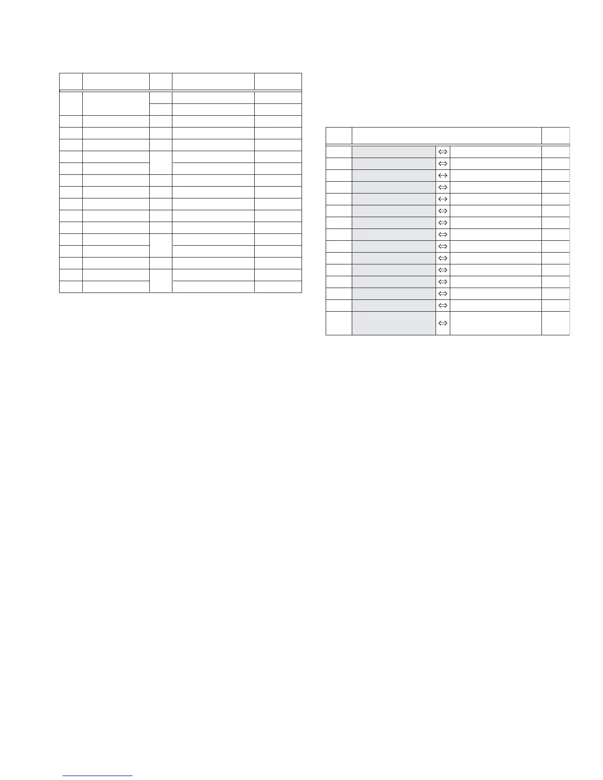
STEP
No.
PART NAME
Fig.
No.
POINT NOTE
[1]
[2]
[3]
[4]
[5]
[6]
[7]
[8]
[9]
[10]
[11]
[12]
[13]
[14]
[15]
[16]
S1a,2(S1b),3(S1c),S1d
L1a,L1b,CN1
CN2a,b,c,S2a,4(S2b)
2(S3)
2(S4),2(L4)
BKT.(HINGE),2(L5)
3(S6),L6
S7a,2(S7b),2(L7a),2(L7b),CN7
GRIP BELT,4(S8),3(L8)
CN9a,S9a,b,c,CN9b
S10a,b,c,L10a,b
2(S11),CN11
S12,L12,CN12
CN13,2(L13)
3(S14),L14a,b
CN15a,b,c,d,e,S15,L15a,b
4(S16)
FA1-1
FA1-2
FA2-1
FA2-2
FA2-3
FA2-4
FA3
FA4
FA5
FA6
FA7
FA8
FA9
FA10
NOTE1a
NOTE1b
NOTE2a,b
-
-
NOTE5
-
NOTE7
NOTE8
NOTE9a,b
NOTE10
NOTE11
NOTE12
NOTE13
-
-
-
CN1 MAIN CN103 OPE CN401 30
CN2a OPE CN403 ZOOM UNIT - 8
CN2b OPE CN404 SPEAKER - 2
CN2c OPE CN402 MONITOR CN7601 18/21
CN7 MAIN CN2601 MIC - 4
CN9a MAIN CN4201 CCD CN5001 20
CN9b MAIN CN7801 VF CN7001 24/23
CN11 REAR CN502 POWER UNIT - 7
CN12 MAIN CN101 REAR CN504 32
CN13 MAIN CN4901 OP BLOCK - 26
CN15a MAIN CN1604 SENSOR - 16
CN15b MAIN CN1603 CAPSTAN MOTOR - 18
CN15c MAIN CN1602 DRUM MOTOR - 11
CN15d MAIN CN3501 HEAD - 8
CN15e MAIN CN1601
LOADING MOTOR
-
8
ROTARY ENCODER SW
CN.
No.
PIN
No.
CONNECTOR
 Loading...