SERVICE MANUAL
No. 86669
February 2002
SPECIFICATIONS
(The specifications shown pertain specifically to the model GR-DVL920)
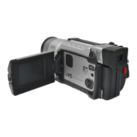
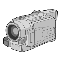
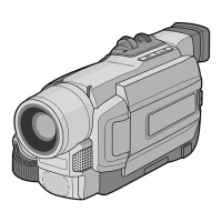
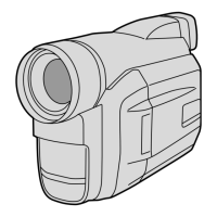
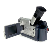
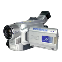
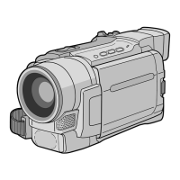
DIGITAL VIDEO CAMERA
Printed in Japan
This service manual is printed on 100% recycled paper.
COPYRIGHT © 2002 VICTOR COMPANY OF JAPAN, LTD.
GR-DVL725U,DVL820U,DVL920U
No. 86669
GR-DVL725U,DVL820U,DVL920U
JVC SERVICE & ENGINEERING COMPANY OF AMERICA
DIVISION OF JVC AMERICAS CORP.
Head office
East Coast
Midwest
West Coast
Atlanta
Hawaii
:
:
:
:
:
:
1700 Valley Road Wayne, New Jersey 07470-9976
10 New Maple Avenue Pine Brook, New Jersey 07058-9641
705 Enterprise Street Aurora, Illinois 60504-8149
5665 Corporate Avenue Cypress, California 90630-0024
1500 Lakes Parkway Lawrenceville, Georgia 30043-5857
2969 Mapunapuna Place Honolulu, Hawaii 96819-2040
(973)317-5000
(973)396-1000
(630)851-7855
(714)229-8011
(770)339-2582
(808)833-5828
JVC CANADA INC.
Head office
Montreal
Vancouver
:
:
:
21 Finchdene Square Scarborough, Ontario M1X 1A7
16800 Rte Trans-Canadienne, Kirkland, Quebec H9H 5G7
13040 Worster Court Richmond, B.C. V6V 2B3
(416)293-1311
(514)871-1311
(604)270-1311
S40895-04
Digital Still Camera Function
Storage media : SD Memory Card/MultiMediaCard
Compression system : Still image : JPEG (compatible)
Moving image : MPEG4 (compatible)
File size : 3 modes (1280 x 960 pixels, 1024 x 768 pixels,
640 x 480 pixels)
Picture quality : 2 modes (FINE/STANDARD)
Approximate number
of storable images : 墌 pg. 27.
Connectors
S-Video
Output : Y : 1 V (p-p), 75 Ω, analog
C : 0.29 V (p-p), 75 Ω, analog
Input : Y : 0.8 V (p-p) – 1.2 V (p-p), 75 Ω, analog
C : 0.2 V (p-p) – 0.4 V (p-p), 75 Ω, analog
AV
Video output : 1 V (p-p), 75 Ω, analog
Video input : 0.8 V (p-p) – 1.2 V (p-p), 75 Ω, analog
Audio output : 300 mV (rms), 1 kΩ, analog, stereo
Audio input : 300 mV (rms), 50 kΩ, analog, stereo
DV
Output : 4-pin, IEEE 1394 compliant
Input : 4-pin, IEEE 1394 compliant
USB : 5-pin
EDIT : ø3.5 mm, 2-pole
AC Adapter
Power requirement
U.S.A. and Canada : AC 120 V`, 60 Hz
Other countries : AC 110 V to 240 V`, 50 Hz/60 Hz
Output : DC 11 V
, 1 A
Specifications shown are for SP mode unless otherwise indicated.
E & O.E. Design and specifications subject to change without notice.
Camcorder
General
Power supply : DC 11.0 V (Using AC Adapter)
DC 7.2 V
(Using battery pack)
Power consumption
LCD monitor off, viewfinder on : Approx. 4.5 W
LCD monitor on, viewfinder off : Approx. 5.7 W
Video light : Approx. 2.8 W
Dimensions (W x H x D) : 79 mm x 89 mm x 184 mm (3-1/8" x 3-9/16" x 7-1/4")
(with the LCD monitor closed and the viewfinder
pushed down)
Weight : Approx. 580 g (1.3 lbs)
Operating temperature : 0°C to 40°C (32°F to 104°F)
Operating humidity : 35% to 80%
Storage temperature : –20°C to 50°C (–4°F to 122°F)
Pickup : 1/3.8" CCD
Lens : F 1.8, f = 3.8 mm to 38 mm, 10:1 power zoom lens
Filter diameter : ø37 mm
LCD monitor : 3.5" diagonally measured, LCD panel/TFT active
matrix system
Viewfinder : Electronic viewfinder with 0.44" color LCD
Speaker : Monaural
Digital Video Camera
Format : DV format (SD mode)
Signal format : NTSC standard
Recording/Playback format : Video: Digital component recording
: Audio: PCM digital recording, 32 kHz 4-channel
(12-bit), 48 kHz 2-channel (16-bit)
Cassette : Mini DV cassette
Tape speed : SP: 18.8 mm/s
LP: 12.5 mm/s
Maximum recording time : SP: 80 min.
(using 80 min. cassette) LP: 120 min.