101
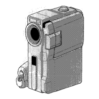
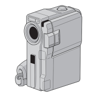
Controls Indicators
Snapshot Mode Button
[SNAPSHOT MODE] ..................... _T_ pg. 24, 32
_ Multi Screen Button
]MULTI S( REEN] ................................. _-T_ pg. 40
(_ Title/Frame ]TITLE] Button .................... _-T_ pg. 69
(_ Operation Switch [ m, [_ I .................. :T _ pg. 19
• Power Zoom Level [T/W] .................. _T_ pg. 26
• Speaker/Headphone Volume
Control [VOL.[ .................................. _-T_ pg. 52
{_, START/STOP/TRANS. Button .......... _-T_ pg. 20, 79
_;_ SNAPSHOT/PHOTO Button ........... _T* pg. 24, 32
(_) Back Light Button [BACK LIGHT[ ......... _-T_ pg. 48
OPEN/EIE( T Switch ............................. _T_ pg. 14
Battery Release Switch
[BATT. RELEASE] .................................. :T* pg. 11
_)oMENU/SETDial]+, ,PUSH] ...... :T*pg. 13,36
• LCD Monitor/Viewfinder Brightness
( ontrol ............................................. :T* pg. 23
(_ Power Switch ...................................... _-T_ pg. 19
(_ Play/Pause Button ]_/llll ...................... _T* pg. 52
Rewind Button [_] ............................ _-T_ pg. 52
_-_ Stop Button 1@] ................................... _-T_ pg. 52
_ Fast-Forward Button [_[ .................... :T* pg. 52
ff_ Lock Button ......................................... _-T_ pg. 19
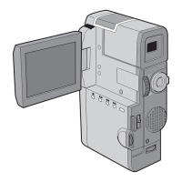
(_ Diopter Adjustment ( ontrol ................. ;T _ pg. 12
Connectors
[] Tally Lamp ........................................... _T_ pg. 20
[] Power Lamp ........................................ _-T_ pg. 20
Other Parts
[] Flash ................................................... _-T_ pg. 34
[] Flash Sensor
Be careful not to cover this area, as it contains a
sensor required by the flash.
[] ( amera Sensor
Be careful not to cover this area; a sensor
necessary for shooting is built-in here.
[] Lens (over
Opens when the viewfinder is pulled out or the
LCD monitor is opened fully.
[] Stereo Microphone .............................. :T* pg. 90
[] Viewfinder ........................................... :T _ pg. 12
[] • Remote sensor .................................. _T* pg. 80
Infrared Transmitter/Receiver ............. _-T_ pg. 78
[] L(D Monitor. ...................................... _T_ pg. 23
[] Speaker ............................................... _-T_ pg. 52
[] Battery Pack Mount ............................. :T _ pg. 11
[] Grip Strap ............................................ _-T_ pg. 12
[] (ard Cover .......................................... _-T_ pg. 16
[] ( assette (over. .................................... :T* pg. 14
Stud Hole ............................................ _-T_ pg. 70
[] Tripod Mounting Socket ................. :T* pg. 18, 70
The connectors 0 to _) are located beneath tile cover.
O Digital Video ( onnector
[DV IN/()UT] (i.link*) .............. _-T_ pg. 72, 73, 75
* i.Link refers to the IEEE1 _94-1995 industry
specification and extensions thereof. The _ logo
is used for products compliant with the i.Link
standa rd.
(_) • Audio/Video Output ( onnector
]AV OUT] ......................................... _T_ pg. 7B
o Headphones Connector [_ ] ............. _-T_ pg. 90
Multi ( onnector
When attached to the Docldng Station, this part is
connected.
 Loading...