70
These are some basic types of connections. When mal<i,tg the connections, refer also tt:l your VCR and TV
instruction manuals,
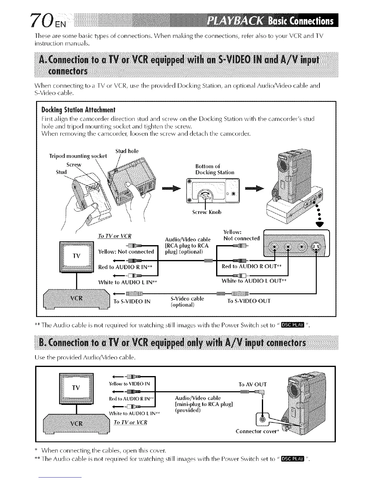
When connecting to a TV or VCR, use the provided Docking Station, an Ol)tional Audio/Video cable and
S-Video cable.
D0¢kingStationAttachment
First align the camct)rder direction stud and screw on the Docking Station with the camcorder's stud
hole and tripod mountJllg socket _nd tighten the screw
When removing the camcordel_ loosen the screw and det_cll the camcorder.
Tripod ,_nwiing socke_
Stu_
f
Stud hole
Bottom of
Doddng Station
I
Screw Knob
Yellow:
To TV or VCR
Audio/Video cable Not connected
Yellow: No plug] (optlona[)
Red toAU_ D,OR OUT**
L _2
White to AUDIO L IN** White to AUD[O L OUT**
To S-VEDEO IN S-Video cable To S-VIDEO OUT
(optional)
** The Audio cable is not required for watching still images with the Power Switch set to "_ ".
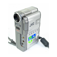
Use the provided Audio/Video cable.
Yellowto VIDEOIN
R Audlo/Video cable
[mini-p[ug to RCA p[ug]
White to AUDIO L IN** (provided)
To TV or VCR
* When connecting the cables, open this cover.
** The Audio cable is not required for watching still images with the Power Switch set to "_ ".