74
EN “.
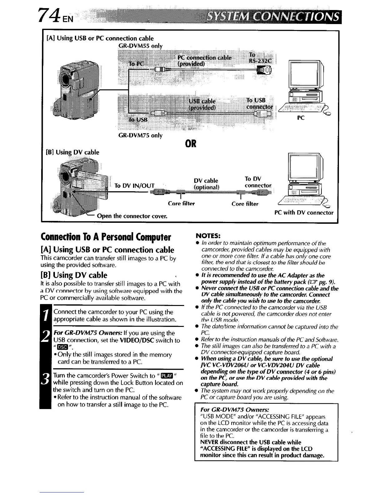
[AI Using USB or PC connection cable
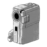
GR-DVM55 only
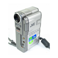
GR-DVM75 only
OR
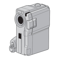
pen the connector cover.
r
Connection To A Personal Computer
[A] Using USB or PC connection cable
This camcorder can transfer still images to a PC by
using the provided software.
[B] Using DV cable
NOTES:
l
In order to maintain optimum performance of the
camcorder, provided cables may be equipped with
one or more core filter. If a cable has only one core
filter, the end that is closest to the filter should be
connected to the camcorder.
l
It is recommended to use the AC Adapter as the
It is also possible to transfer still images to a PC with
a DV connector by using software equipped with the
PC or commercially available software.
I.
Connect the camcorder to your PC using the
appropriate cable as shown in the illustration.
For GR-DVM75 Owners: If you are using the
US6 connection, set the VIDEO/DSC switch to
“=‘I.
*Only the still images stored in the memory
card can be transferred to a PC.
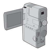
Turn the camcorder’s Power Switch to fl m n
while pressing down the Lock Button located on
the switch and turn on the PC.
l
Refer to the instruction manual of the software
on how to transfer a still image to the PC.
power supply instead of the battery pack (W pg. 9).
l
Never connect the USE or PC connection cab/e and the
DV cab/e simultaneous/y to the camcorder. Connect
on/y the cable you wish to use to the camcorder.
l
If the PC connected to the camcorder via the USB
cable is not powered, the camcorder does not enter
the USB mode.
0 The date/time information cannot be captured into the
PC.
l
Refer to the instruction manuals of the PC and Software
l
The still images can also be transferred to a PC with a
DV connector-equipped capture board.
l
When using a DV cable, be sure to use the optional
IVC VC-VDV206U or VC-VDV204U DV cable
depending on the type of DV connector (4 or 6 pins)
on the PC, or use the DV cab/e provided with the
capture board.
l
The system may not work properly depending on the
PC or capture board you are using.
For CR-DVM75 Owners:
“USB MODE” and/or “ACCESSING FILE” appears
on the LCD monitor while the PC is accessing data
in the camcorder or the camcorder is transferring a
file to the PC.
NEVER disconnect the USB cable while
“ACCESSING FILE” is displayed on the LCD
monitor since this can result in product damage.
 Loading...