EN
75
Open the connector
I I
To DV IN/OUT To DV IN/OUT
: :
Core filter
DV cable
(optional)
Core filter
To DV IN To DV IN
connector connector
To DV
connector
Digital Printer
PC connection
PC
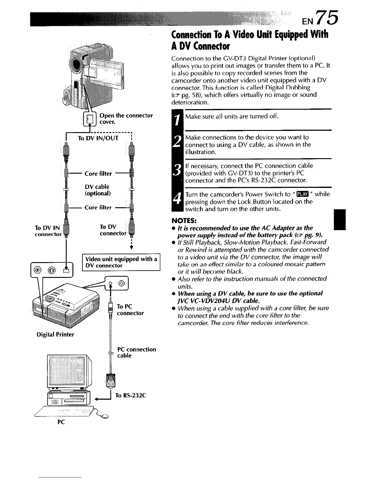
Connection To A Video Unit Equipped With
A DV Connector
Connection to the GV-DT3 Digital Printer (optional)
allows you to print out images or transfer them to a PC. It
is also possible to copy recorded scenes from the
camcorder onto another video unit equipped with a DV
connector. This function is called Digital Dubbing
(m pg. 58), which offers virtually no image or sound
deterioration.
Make sure all units are turned off.
Wake connections to the device you want to
connect to using a DV cable, as shown in the
illustration.
I
1
If necessary, connect the PC connection cable
[provided with CV-DT3) to the printer’s PC
connector and the PC’s RS-232C connector.
Turn the camcorder’s Power Switch to I‘m“ while
pressing down the Lock Button located on the
~ ;witch and turn on the other units.
NOTES:
l
It is recommended to use the AC Adapter as the
power supply instead of the battery pack (w pg. 9).
l
If Still Playback, Slow-Motion Playback, Fast-Forward
or Rewind is attempted with the camcorder connected
to a video unit via the DV connector, the image will
take on an effect similar to a coloured mosaic pattern
or it will become black.
l
Also refer to the instruction manuals of the connected
units.
l
When using a DV cable, be sure to use the optional
jVC VC-VDV204U DV cable.
l
When using a cab/e supplied with a core filter, be sure
to connect the end with the core filter to the
camcorder. The core filter reduces interference.