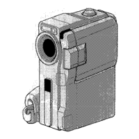
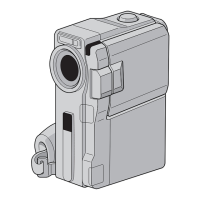
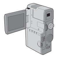
Controls
@ E-MAIL CLIP REC Button
(GR-DVM75 only).
...............................
rz pg. 61
@ D. SOUND PLAY Button
(GR-DVM75 only). ...............................
m pg. 56
@
l
MENU Wheel [+, -, PUSH]
..............
.cr pg. 38
l
LCD Monitor Brightness
Control [+, -1 ....................................
= pg. 18
@ l
Power Zoom Lever [T/W]
.................
.= pg. 19
l
Speaker Volume Control
[VOL.]
...............................................
= pg. 21
@ Power Switch
[O, 0, m,OFF]
............................
“rpg. 16
@ Lock Button
.........................................
=T pg. 16
@ Recording Start/Stop Button
.................
E pg. 18
@ Snapshot Button
[SNAPSHOT]
...............
ai‘ pg. 26, 27, 50, 59, 60
@
l
FOCUS Button ..................................
c? pg. 51
l
BLANK Button
...................................
it? pg. 24
Q Battery Release Switch
[BATT. RELEASE] ....................................
= pg. 8
@ OPEN/EJECT Switch
.............................
= pg. 12
@I SELECT Button (CR-DVM75 only).
.. E pg. 30, 32
@ JUMP Button (GR-DVM75 only)
..........
rr pg. 30
@ INDEX Button
(CR-DVM75 only).
......................... = pg.
30, 56
l
Play/Pause Button
[)/II] ..................
c7 pg. 21
l
NIGHT-ALIVE
Button..
.......................
= pg.
45
l
Fast-Forward Button
[w] ...............
a? pg. 21
l
PROGRAM AE
Button .......................
rr pg. 46
l
Stop Button [ml .................................
~3 pg. 21
l
BACKLIGHT Button..
.........................
= pg. 52
l
Rewind Button
[++I .......................
= pg. 21
l
EXPOSURE Button.. ...........................
OT pg. 52
@ VIDEO/DSC Switch [VIDEO, ml
(GR-DVM75 only) . . . . . . . . . . . . . . . . . . . . . . . . . . . . . . . . rr pg.
16
@ CARD OPEN Switch
(GR-DVM75 only) . . . . . . . . . . . . . . . . . . . . . . . . . . . . . . . . rr pg.
14
@ Diopter Adjustment Control . . . . . . . . . . . . . . . . 31 pg.
10
Connectors
The connectors @to @ are located beneath a cover.
@ Digital Video Connector
[DV IN/OUT]
(i.link*) . . . . . . . . . . . . . . ILL pg. 58, 74, 75
* i.Link refers to the IEEE1 394-l 995 industr):
specification and extensions thereof. The 6 logo
is used for products compliant with the i.Link
standard.
@I
l
Audio/Video Input (CR-DVM75 only)/
Output Connector
[AV’IN/OUT or AV OUT] . . . . . . ~1 pg. 22, 57, 70
l
Headohone Connector [l) I
(GR-DVM75
only) .............................
ID pg. 66
@ DC Input Connector [DC IN]
............. IL? pg. 8, 9
Indicators
q
Tally Lamp
.....................................
in pg. 18, 40
q
Power Lamp..
.................................
m pg. 16, 18
H CHARGE
Lamp ......................................
ID pg. 8
Other Parts
q
LCD Monitor..
................................
LTr pg. 18, 19
q
Battery Pack/Jack Box Mount
........... m pg. 8, 23
q
Speaker..
..............................................
in pg. 21
ED Camera Sensor
Be careful not to cover this area, a sensor
necessary for shooting is built-in here.
q
Stereo Microphone ..............................
Ib pg. 66
q
Flash (GR-DVM75
only). ......................
LD pg. 54
q
Flash Sensor (CR-DVM75 only)
Be careful not to cover this area, as it contains a
sensor required by the flash.
q
Lens
q
Lens Protector
When using an optional lens filter (commercially
available), you must first detach the lens
protector.
q
Remote
Sensor .....................................
m pg. 62
q
Grip Strap
............................................
u pg. 10
q
Viewfinder
...........................................
ID pg. 10
q
Viewfinder Cleaning Hatch
..................
= pg. 84
q
Memory Card Cover
(CR-DVM75
only). ...............................
a7 pg. 14
q
Cassette Holder Cover
.........................
UT pg. 12
q
Tripod
Mounting Socket .......................
e pg. 10
 Loading...