(No.YF034)1-7
3.2.2 ASSEMBLY/DISASSEMBLY OF CABINET PARTS AND ELECTRICAL PARTS
zDisassembly procedure
NOTE1:
Before removing the CASSETTE COVER ASSEMBLY, re-
move the GRIP BELT ASSEMBLY.
NOTE4a:
During the procedure, be careful in handling the parts.
NOTE4b:
In attaching the SIDE COVER (L) ASSEMBLY, attach the
COVER (JACK, DV) ASSEMBLY at the same time.
NOTE5:
In removing the UPPER CASE ASSEMBLY, be careful not
to damage connectors.
NOTE6:
In attaching the FRONT COVER ASSEMBLY, be careful not
to cut or damage wires.
NOTE7:
In attaching the MIC ASSEMBLY, be careful not to cut or
damage wires.
NOTE8:
When attaching the REAR COVER ASSEMBLY, be careful
about the position of switch.
NOTE9:
For the disassembly procedure of the MONITOR ASSEMBLY,
see "3.2.3 DISASSEMBLY of [9] MONITOR ASSEMBLY"
NOTE12a:
Pull out the VF ASSEMBLY, and remove one screw (No.46).
NOTE12b:
For the disassembly procedure of the VF ASSEMBLY, see
"3.2.4 DISASSMBLY of [12] VF ASSEMBLY"
NOTE13:
For the disassembly procedure of the OP BLOCK ASSEM-
BLY/CCD BOARD ASSEMBLY, see "3.2.5 DISASSEMBLY
of [13] OP BLOCK ASSEMBLY/CCD BOARD ASSEMBLY"
NOTE14:
In removing the MAIN BOARD ASSEMBLY, remove the SPACER.
NOTE16:
Be careful in handling the parts.
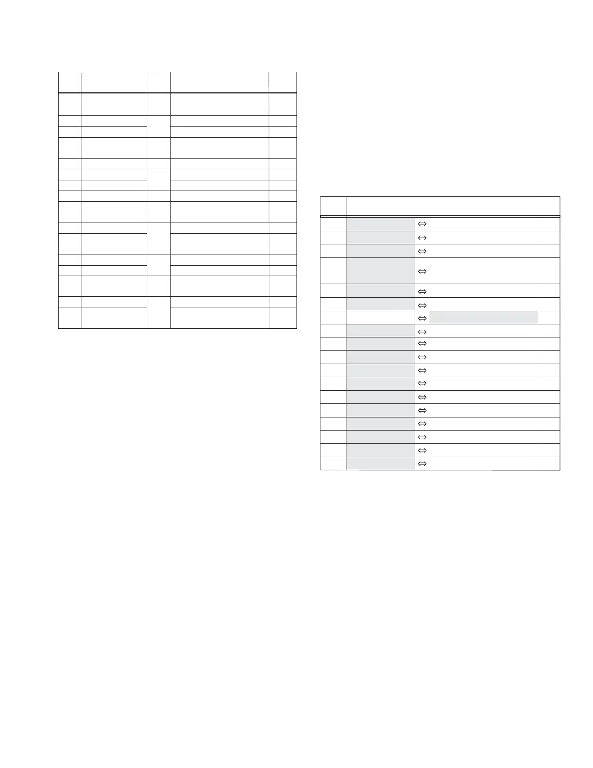
zDestination of connectors
STEP
No.
PART NAME
Fig.
No.
POINT NOTE
[1]
[2]
[3]
[4]
[5]
[6]
[7]
[8]
[9]
[10]
[11]
[12]
[13]
[14]
[15]
[16]
CASSETTE COVER ASSY
SIDE COVER(R)
TOP COVER
SIDE COVER(L)ASSY
UPPER CASE ASSY
FRONT COVER ASSY
MIC ASSY
REAR COVER ASSY
MONITOR BOARD
SD BOARD ASSY
LOWER UNIT ASSY
(INCLUDE VF ASSY/OP BLOCK ASSY)
VF ASSY
OP BLOCK ASSY/CCD BOARD ASSY
MAIN BOARD ASSY
MDA BOARD ASSY
MECHANISM ASSY
GRIP BELT ASSY,2(S1),HOOK(F)
(S1),L1a,COVER(ADJ),4(S1),L1b
(S2a),(S2b),L2a,L2b
2(S3),2(L3)
6(S4a),(S4b),(S4c),COVER(DV)ASSY
JACK COVER ASSY
(S5),L5,COVER(JIG CON),4(S5),CN5
5(S6),CN6
2(S7)
2(S8),3(L8),CN8
2(S9),3(L9a),BKT(TOP)ASSY
CN9a,b,6(S9),L9b,2(L9c)
CN10,(S10)
CN11a,b,c,d,e,3(S11)
4(S12)
(S13a),2(S13b),2(L13)
2(S14),2(L14a),SHIELD COVER
CN14a,b,c,L14b
CN15a,b,c,d,2(S15)
(S16a),BKT(PRE-REC),3(S16b)
BKT(MECHA)ASSY
Fig.C1
Fig.C2
Fig.C3
Fig.C4
Fig.C5
Fig.C6
Fig.C7
Fig.C8
Fig.C9
Fig.C10
Fig.C11
NOTE1
-
-
NOTE4a, b
NOTE5
NOTE6
NOTE7
NOTE8
NOTE9
-
-
NOTE12a, b
NOTE13
NOTE14
-
NOTE16
CN.NO.
CONNECTOR
PIN
NO.
CN5 MAIN CN115 SUB OPE UNIT - 6
CN6 MAIN CN111 MIC ASSY - 4
CN8 MAIN CN109 CAMERA OPE UNIT - 13
CN9a MAIN CN104 MONITOR
CN7601
39/20,
/CN7602 20
CN9b MAIN CN108 POWER OPE UNIT - 7
CN10 MAIN CN114 SD CN701 12
CN11a MAIN CN112 FRONT CN401 12
CN11b MAIN CN107 OP BLOCK ASSY - 28
CN11c MAIN CN102 CCD CN5501 20
CN11d MAIN CN101 BATT. TERM. - 21
CN11e MAIN CN113 VF FPC ASSY - 22/20
CN14a MAIN CN106 SENSOR - 16
CN14b MAIN CN103 MDA CN305 30
CN14c MAIN CN110 HEAD - 8
CN15a MDA CN301 CAPSTAN MOTOR - 18
CN15b MDA CN302 DRUM MOTOR - 11
CN15c MDA CN303
ROTARY ENCODER SW
- 6
CN15d MDA CN304 LOADING MOTOR - 6