(No.YF163)1-7
3.2.2 ASSEMBLY/DISASSEMBLY OF CABINET PARTS AND ELECTRICAL PARTS
z Disassembly procedure
NOTE2a:
During the procedure, leave the GRIP BELT removed from
the hook.
NOTE2b:
When removing the HDD COVER ASSY, leave the JACK
COVER (DC) released.
NOTE2c:
During the procedure, be careful not to damage the tabs.
NOTE2d:
When removing the HDD COVER ASSY, be careful in han-
dling as the HDD may come off.
NOTE3a:
During the procedure, be careful in handling the HDD. Make
sure not to give any shock to the HDD.
NOTE3b:
When attaching the HDD, check the positions of the marks,
and be careful with the GEL lift.
NOTE5:
The screw (No.11) is located under the JACK COVER
(REAR).
NOTE6:
Do not disassemble the ZOOM UNIT if not needed as the
SHIELD (ZOOM) is attached to the terminals.
NOTE7:
When removing the REAR UNIT, be careful in handling as
the JACK COVER (REAR) comes off together.
NOTE10:
When attaching the MIC, be careful with the MIC wiring.
NOTE12a:
Remove the screw (No.30), which tightens up the FPC, be-
fore connecting/ disconnecting the FPC to/ from the connec-
tor.
NOTE12b:
Refer to 3.2.3 ASSEMBLY/DISASSEMBLY OF [12] MONI-
TOR ASSEMBLY for the disassembly of the MONITOR AS-
SY.
NOTE13a:
During the procedure, be careful in handling the EARTH
PLATE OPE.
NOTE13b:
When attaching the two switches (POWER, MODE), be
careful with the attachment locations. Attach the levers and
switches fixed to one direction as they can be fixed (except
the MODE switch lever). After the attachment, check the op-
eration by moving the switch levers.
NOTE13c:
When attaching the SPEAKER WIRE, be careful in the wir-
ing and not to catch the WIRE in between.
NOTE16:
When attaching the SPEAKER, be careful with the attach-
ment location. Attach the OPE BOARD ASSY first, and then
follow the figure for the SPKEAKER wiring.
NOTE17:
When attaching the MAIN BOARD ASSY, make sure to in-
sert the corner of the MAIN BOARD ASSY into the slit of the
FRAME ASSY.
NOTE18a:
During the procedure, be careful not to damage the EARTH
TERMINAL.
NOTE18b:
Refer to 3.2.4 ASSEMBLY/DISASSEMBLY OF [18] OP
BLOCK ASSEMBLY/CCD BOARD ASSEMBLY.
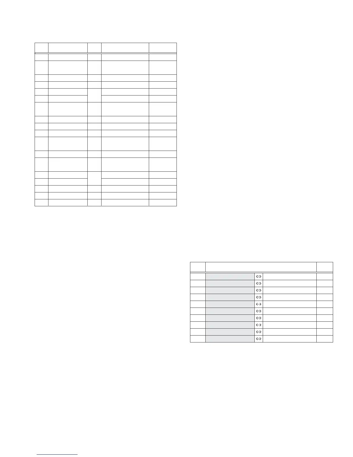
z Destination of connectors
[1]
[2]
[3]
[4]
[5]
[6]
[7]
[8]
[9]
[10]
[11]
[12]
[13]
[14]
[15]
[16]
[17]
[18]
CA1
FA1
FA2
FA3
FA4
FA5
FA6
FA7
FA8
FA9
UA1
UA2
UA3
UA4
FA10
FA11
-
NOTE2a,b,c,d
NOTE3a,b
-
NOTE5
NOTE6
NOTE7
-
-
NOTE10
-
NOTE12a,b
NOTE13a,b,c
-
-
NOTE16
NOTE17
NOTE18a,b
BOTTOM COVER ASSY
HDD COVER ASSY
HDD
HDD CASE ASSY
TOP COVER(ZOOM)
ZOOM UNIT
REAR BOARD ASSY
MONI. LOCK CASE ASSY
FRONT COVER ASSY
MIC
UPPER ASSY
MONITOR ASSY
OPE BOARD ASSY
TOP COVER(U) ASSY
POWER SW ASSY
SPEAKER
MAIN BOARD ASSY
OP BLOCK ASSY
3(S1),3(L1)
GRIP BELT,2(S2),
JACK COVER(DC),L2a,b,c,d
CN3
3(S4a),2(S4b)
CN5,JACK COVER(REAR),S5,L5a,b
SHIELD(ZOOM),2(S6),2(L6)
4(S7),2(L7a),JACK COVER(REAR),
CN7a,b,L7b,REAR UNIT
2(S8),2(L8)
2(S9a),S9b,CN9
2(S10),L10,BKT(MIC)
S11,L11a,SHIELD(FRAME),
4(S11),L11b,CN11
S12a,CN12,2(S12b),2(L12)
S13,INTER RUPTER,S13
EARTH PLATE OPE,2(S13),CN13,L13
2(S14),2(L14)
2(S15),2(L15)
4(S16),L16a,b,BKT(UPPER)
CN17a,b,2(S17)
3(S18)
STEP
No.
PART NAME
Fig.
No.
POINT NOTE
CN3 HDD - MAIN CN102 40
CN5 MAIN CN104 ZOOM UNIT - 6
CN7a MAIN CN103 REAR CN6001 53
CN7b REAR CN6002 TRIG SW - 6
CN9 MAIN CN107 MIC - 4
CN11 MAIN CN101 OPERATION CN401 50
CN12 OPERATION CN402 MONI-BL CN7601,7602 24/12,12
CN13 OPERATION CN403 SPEAKER - 2
CN17a MAIN CN105 CCD CN5201 24
CN17b MAIN CN106 OP BLOCK - 22
CN.
No.
PIN
No.
CONNECTOR
 Loading...