1-8 (No.MB161)
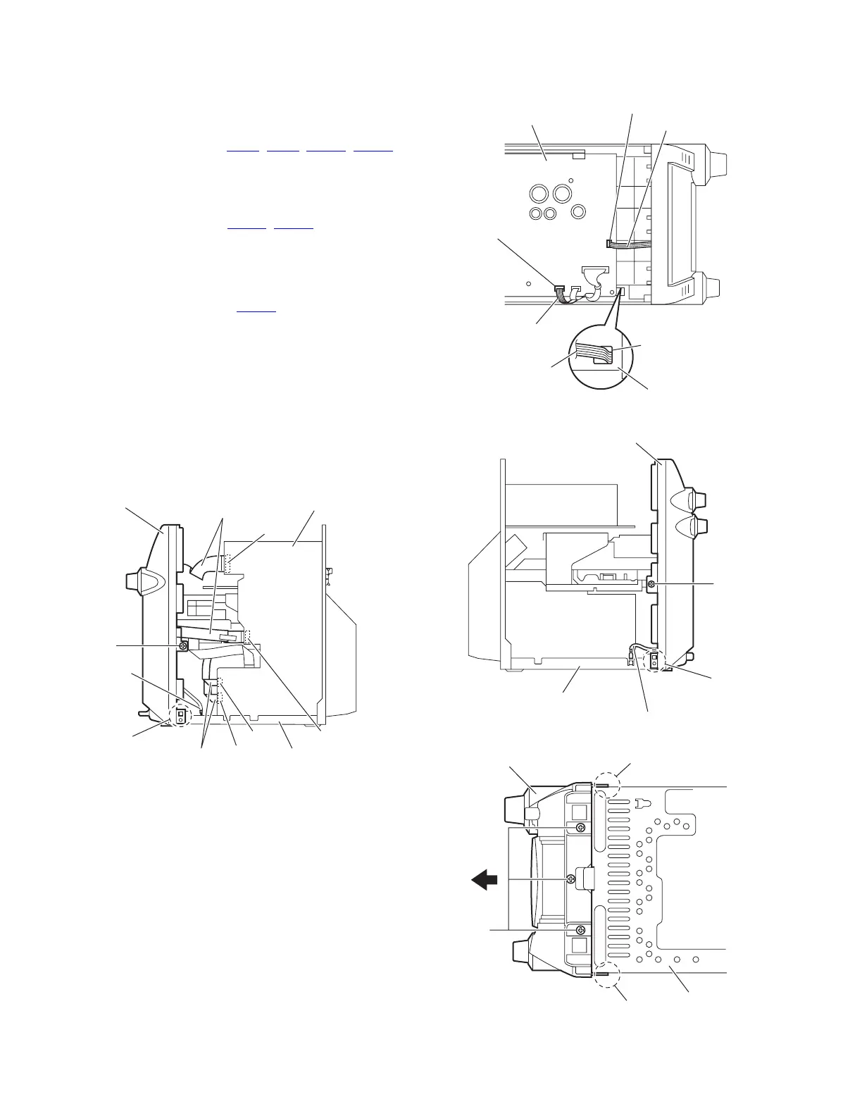
3.1.2 Removing the front panel assembly
(See Figs.4 to 7)
• Prior to performing the following procedures, remove the metal
cover.
(1) From the right side of the main body, disconnect the card
wires from the connectors (CN43
, CN44, CN802, CN803)
on the main board. (See Fig.4.)
(2) Disconnect the earth wire from the chassis base. (See
Fig.4.)
(3) From the top side of the main body, disconnect the parallel
wires from the connectors (CN201
, CN205) on the bridge
board. (See Fig.5.)
Reference:
When reassembling, pass the parallel wire through the
hole a on the plastic chassis before connecting the par-
allel wire to the connector CN201
on the bridge board.
(See Fig.5.)
(4) Disconnect the earth wire from the chassis base. (See
Fig.6.)
(5) From the both sides of the main body, remove the two
screws C attaching the front panel assembly. (See Figs.4
and 6.)
(6) From the bottom side of the main body, remove the three
screws D attaching the front panel assembly. (See Fig.7.)
(7) Release the joints b of the front panel assembly from the
chassis base and remove the front panel assembly in the
direction of the arrow. (See Figs.4,6 and 7.)
Fig.4
Fig.5
Fig.6
Fig.7
Front panel assembly
Card wires
Card wires
Earth wire
Chassis base
Main board
CN803
CN802
CN43
CN44
b
C
Parallel wire
Parallel wire
Plastic chassis
Bridge board
CN201
CN205
a
Parallel wire
Front panel assembly
Earth wire
Chassis base
b
C
Front panel assembly
Chassis base
b
b
D
 Loading...