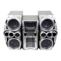
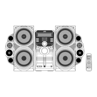
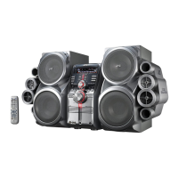
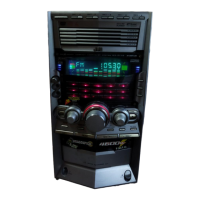
1-17
HX-Z3
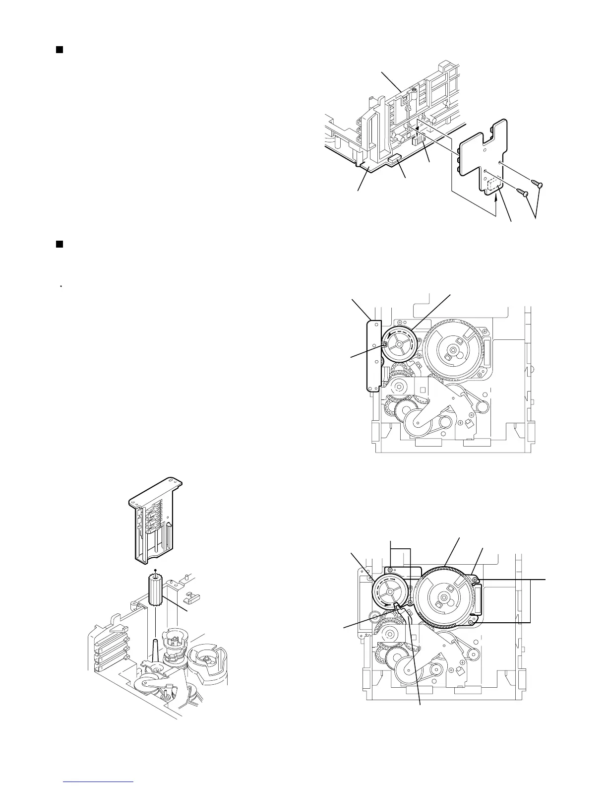
Remove the two screws G retaining the tray select
switch board.
Disconnect the tray select switch board from
connector CN854 on the CD servo control board
.
1.
2.
Removing the try select switch board
(See Fig.14)
Remove the CD loading mechanism assembly.
While turning the cam gear q , align the Paul r
position of the drive unit to the notch position on the
cam gear q .
Pull out the drive unit and cylinder gear .
While turning the cam gear q , align the Paul s
position of the select lever to the notch position on
the cam gear q .
Remove the four screws H retaining the cam
unit(cam gear q and cams R1/R2 assembly).
1.
2.
3.
4.
Removing the cam unit
(See Fig.15 ~17 )
Cam gear q
Drive unit
r
G
H
H
Chassis assembly
Tray select
switch board
CD servo
control board
CN854
CN851
CN804
Cylinder gear
Drive unit
Fig.17
Select lever
Cams R1, R2 assembly
Cam unit
Cam gear q
s
Fig.15
Fig.14
Fig.16
 Loading...