1-12 (No.MA140)
3.2 CD mechanism assembly section
• Remove the CD mechanism assembly from the main body.
(See "3.1.5 Removing the CD mechanism assembly".)
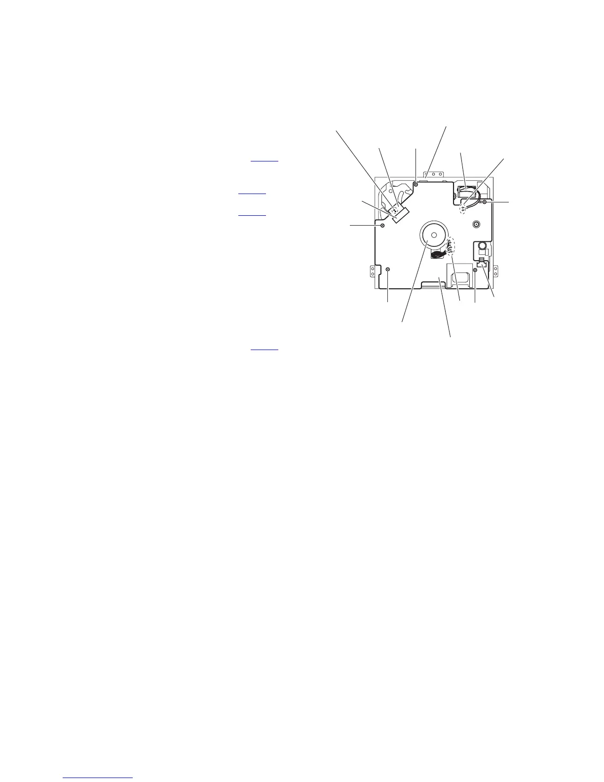
3.2.1 Removing the mechanism control board
(See Fig.1)
(1) From the bottom side of the CD mechanism assembly, sol-
der the short sections on the flexible wire.
Caution:
Solder the short sections on the flexible wire before dis-
connecting the flexible wire from the connector CN601
on the mechanism control board. If you do not follow this
instruction, the CD pickup may be damaged.
(2) Disconnect the flexible wire from the connector CN601
on
the mechanism control board.
(3) Disconnect the flexible wire from the connector CN602
on
the mechanism control board.
(4) Remove the solders from the soldered sections a on the
mechanism control board and remove the wires of the feed
motor.
(5) Remove the solders from the soldered sections b on the
mechanism control board, and remove each wire of the
spindle motor and other parts.
(6) Remove the five screws A attaching the mechanism con-
trol board.
Caution:
When reassembling, remove the solders from the short sec-
tions after connecting the flexible wire to the connector CN601
on the mechanism control board.
Fig.1
A
A
CN601
Short sections
Feed motor
Flexible wire
CD mechanism assembly
A
Mechanism control board
b
Spindle motor
A
CN602
A
a
 Loading...