(No.MA140)1-13
3.2.2 Removing the top cover
(See Fig.2)
(1) From the back side of the CD mechanism assembly, re-
move the two screws B attaching the top cover.
(2) Take out the top cover in an upward direction.
Reference:
When attaching the top cover, set the sections c of the top cov-
er under the bending sections d of the chassis base 2.
3.2.3 Removing the mechanism section
(See Figs.2 to 4)
• Remove the mechanism control board and top cover.
(1) From the front side of the CD mechanism assembly, re-
move the two screws C attaching the right and left stop-
pers. (See Fig.2.)
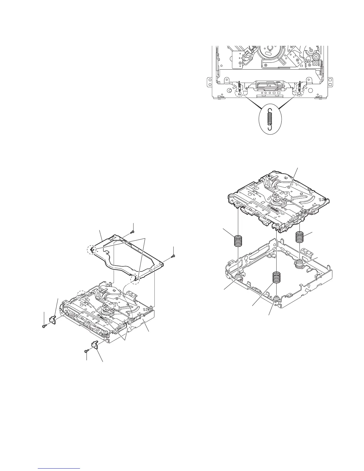
(2) Remove the two floating springs on the bottom side of the
CD mechanism assembly. (See Fig.3.)
(3) Take out the mechanism section in an upward direction
and remove the three damper springs from the dampers.
(See Fig.4.)
Caution:
• When reassembling the mechanism section, reattach the
damper springs to the dampers respectively and insert the
three shafts on the bottom of the mechanism section to the
dampers. (See Fig.4.)
• Before inserting the shaft to the dampers, apply IPA to the
hole of damper.
Fig.2
Fig.3
Fig.4
B
Top cover
Stopper
Stopper
C
C
B
d
c
Chassis base 2
Floating spring
Mechanism section
Dampe
(Yellow)
Damper
(Black)
Damper
(Black)
Damper
spring(F)
(Green)
Damper
spring(F)
(Green)
Damper
spring(R)
(Red)
 Loading...