1-16 (No.MA140)
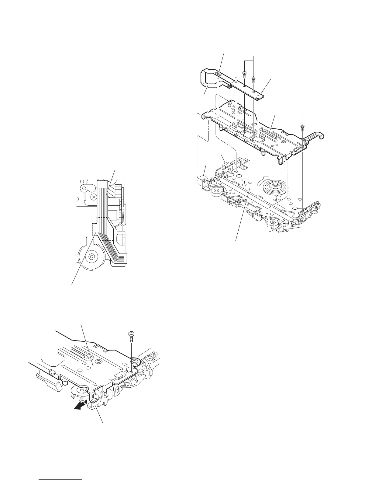
3.2.6 Removing the front unit
(See Figs10 to 12)
• Remove the mechanism control board, top cover and mecha-
nism section.
(1) From the bottom side of the mechanism section, remove
the double-stick tape fixing the flexible wire. (See Fig.10.)
(2) From the top side of the mechanism section, remove the
screw D attaching the front unit 2. (See Figs.11 and 12.)
(3) Move the front unit 2 toward the front to release the joint i.
(See Figs.11 and 12.)
(4) Release two joints j and k on the right side of the CD chas-
sis assembly. (See Fig.12.)
(5) Take out the front unit 2 in an upward direction.
(6) Remove the double-stick tape fixing the flexible wire and
remove the two screws E attaching the switch wire. (See
Fig.12.)
Reference:
You can remove the switch wire only without removing the
front unit 2.
Fig.10
Fig.11
Fig.12
Flexible wire
Double-stick tape
D
Front unit 2
i
i
Front unit 2
Switch wire
j
D
E
k
Double-stick tape
CD chassis assembly
Flexible
wire
 Loading...