(No.MA165)1-15
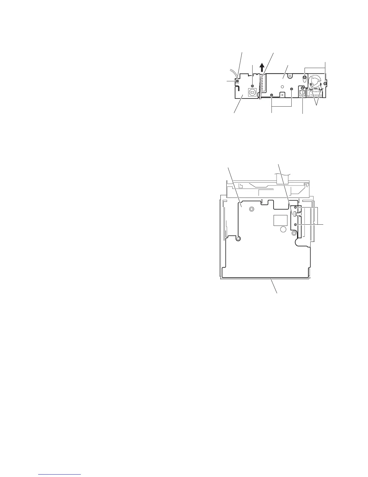
3.1.12 Removing the rear bracket
(See Fig.18)
• Remove the panel assembly, side heat sink, top chassis as-
sembly, loading unit assembly, arm bracket assemblies (L)/(R)
and main board.
(1) From the back side of the main board, remove the two
screws Q attaching the rear heat sink.
(2) Remove the three screws R, screw R' and screw S attach-
ing the rear bracket.
Reference:
When attaching the screw R', attach the wire holder with
it as before.
(3) Remove the joints f of the rear bracket in the direction of
the arrow.
(4) Remove the car cable in the direction of the arrow from the
rear bracket.
Fig.18
3.1.13 Removing the panel switch board
(See Fig.19)
• Remove the panel assembly, side heat sink, top chassis as-
sembly, loading unit assembly, arm bracket assemblies (L)/(R)
and main board.
(1) From the inside of the bottom chassis assembly, take out
the insulator.
(2) Remove the two screws T attaching the panel switch
board.
(3) Take out the panel switch board from the bottom chassis
assembly.
Fig.19
Wire holder
Rear bracket
f
R
R'
Q
Car cable
S
R
Rear heat sink
T
Panel switch board
Insulator
Bottom chassis assembly
 Loading...