3
ENGLISH FRANÇAIS
B
Rear ground
terminal
Borne arrière de
masse
Line out (see diagram )
Sortie de ligne
(voir le diagramme )
VIDEO OUT
(see diagram
/ voir le diagramme )
LINE IN
(see diagram
/ voir le diagramme )
DIGITAL OUT (see diagram
/
voir le diagramme )
C
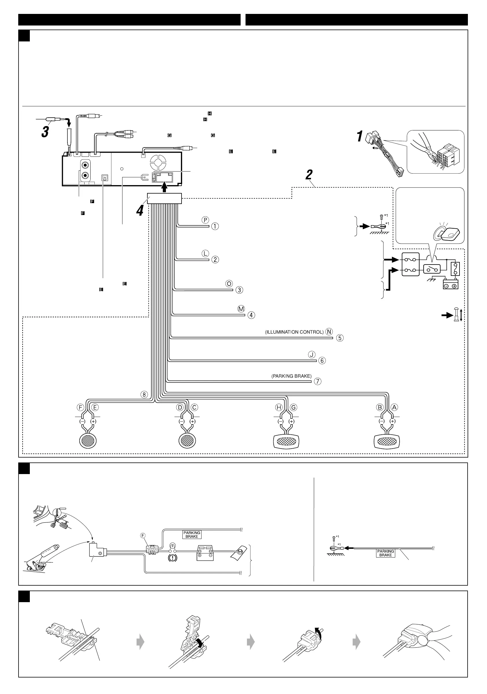
When installing the monitor in a location where it can be seen by the driver
Lorsqu’on installe le moniteur à un emplacement où il peut être vu du conducteur
Connect the parking brake wire to the parking brake system built in the car.
Connectez le fil de frein de stationnement au système de frein de stationnement.
Connecting the crimp connector / Connexion de la cosse sertie
D
Wire connecting the battery and the parking brake switch.
Fil connectant la batterie et l’interrupteur de frein de stationnement.
Attach the parking brake wire to this point.
Attachez le fil du frein de stationnement ici.
Contact the metallic part of the crimp to the wires inside.
Mettez en contact la partie métallique de la cosse à sertir et des
fils intérieurs.
Pinch the crimp firmly.
Pincez la cosse à sertir fermement.
Parking brake
Frein de stationnement
Parking brake wire (light green)
Fil du frein de stationnement
(vert clair)
To metallic body or chassis
of the car
Vers corps métallique ou
châssis de la voiture
Parking brake switch (inside the car)
Commutateur de frein de stationnement
(intérieur de la voiture)
When installing the monitor in a location where it cannot
be seen by the driver
Lorsqu’on installe le moniteur à un emplacement où il ne
peut pas être vu du conducteur
Connect the parking brake wire to metallic body or chassis of
the car.
Connectez le fil du frein de stationnement au corps métallique ou
châssis du véhicule.
Parking brake wire (light green)
Fil du frein de stationnement (vert clair)
Before connecting: Check the wiring in the vehicle carefully. Incorrect connection may cause
serious damage to this receiver.
The leads of the power cord and those of the connector from the car body may be different in
color.
1 Cut the ISO connector.
2 Connect the colored leads of the power cord in the order specified in the illustration below.
3 Connect the aerial cord.
4 Finally connect the wiring harness to the receiver.
Connections without using the ISO connectors / Connexions sans l’utilisation des connecteurs ISO
Avant de commencer la connexion: Vérifiez attentivement le câblage du véhicule. Une
connexion incorrecte peut endommager sérieusement l’appareil.
Le fil du cordon d’alimentation et ceux des connecteurs du châssis de la voiture peuvent être différents
en couleur.
1 Coupez le connecteur ISO.
2
Connectez les fils colorés du cordon d’alimentation dans l’ordre spécifié sur l’illustration ci-dessous.
3 Connectez le cordon d’antenne.
4 Finalement, connectez le faisceau de fils à l’appareil.
To steering wheel remote controller (see diagram )
Pour la télécommande de volant (voir le diagramme )
15 A fuse
Fusible 15 A
Black
Noir
To metallic body or chassis of the car
Vers corps métallique ou châssis de la voiture
Blue with white stripe
Bleu avec bande blanche
Red
Rouge
Yellow
*
2
Jaune*
2
To a live terminal in the fuse block connecting to the car battery
(bypassing the ignition switch) (constant 12 V)
À une borne sous tension du porte-fusible connectée à la batterie de la
voiture (en dérivant l’interrupteur d’allumage) (12 V constant)
To an accessory terminal in the fuse block
Vers borne accessoire du porte-fusible
To the remote lead of other equipment or power aerial if any (200 mA max.)
Au fil de télécommande de l’autre appareil ou à l’antenne automatique s’il y en a une
(200 mA max.)
Orange with white stripe
Orange avec bande blanche
To car light control switch
À l’interrupteur d’éclairage de la voiture
*
2
Before checking the operation of this receiver
prior to installation, this lead must be connected,
otherwise power cannot be turned on.
*
2
Pour vérifier le fonctionnement de cet appareil avant
installation, ce fil doit être raccordé, sinon l’appareil
ne peut pas être mis sous tension.
*
1
Not included for this receiver
*
1
Non fourni avec cet appareil
Ignition switch
Interrupteur d’allumage
Fuse block
Porte-fusible
Brown
Marron
To cellular phone system
À un système de téléphone cellulaire
To parking brake, metallic body or chassis of the car
Au frein de stationnement, corps métallique ou châssis du véhicule
Light green
Vert clair
Purple
Violet
Purple with black stripe
Violet avec bande noire
Green
Vert
Green with black stripe
Vert avec bande noire
Gray
Gris
Gray with black stripe
Gris avec bande noire
White
Blanc
White with black stripe
Blanc avec bande noire
Left speaker (front)
Enceinte gauche (avant)
Right speaker (front)
Enceinte droit (avant)
Left speaker (rear)
Enceinte gauche (arrière)
Right speaker (rear)
Enceinte droit (arrière)
Connecting the parking brake wire / Connexion du cordon de frein de stationnement
Instal3-4_DV5101_007A_f.indd 4Instal3-4_DV5101_007A_f.indd 4 12/24/04 4:08:57 PM12/24/04 4:08:57 PM
 Loading...