(No.MA122)1-9
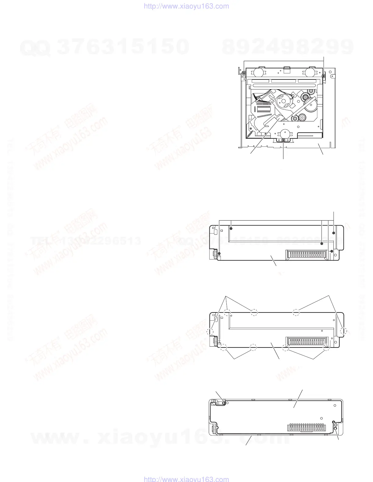
3.1.8 Removing the CD mechanism assembly
(See Fig.9)
• Prior to performing the following procedure, remove the front
panel assembly, front chassis assembly, side panel, bottom
cover, rear bracket, main board and CD mecha control board.
(1) Remove the three screws K attaching the top chassis.
(2) Take out the CD mechanism assembly.
Fig.9
3.1.9 Removing the switch board
(See Figs.10 to 12)
• Prior to performing the following procedure, remove the front
panel assembly.
(1) Remove the five screws L attaching the front panel assem-
bly. (See Fig.10)
(2) Release the nine joints h, and take out the rear cover. (See
Fig.11)
(3) Release the joint i, and take out the switch board. (See
Fig.12)
Note:
When removing the rear cover assembly and switch board, be
careful not to lose the compression spring and comp. spring.
(See Fig.12)
Fig.10
Fig.11
Fig.12
K
K
CD mechanism assembly
Top chassis
L
Rear cover
Rear cover
Joint h
Joint h
Joint h
Joint h
Switch board
Compression spring
Comp. spring
Front panel assembly
w
w
w
.
x
i
a
o
y
u
1
6
3
.
c
o
m
Q
Q
3
7
6
3
1
5
1
5
0
9
9
2
8
9
4
2
9
8
T
E
L
1
3
9
4
2
2
9
6
5
1
3
9
9
2
8
9
4
2
9
8
0
5
1
5
1
3
6
7
3
Q
Q
TEL 13942296513 QQ 376315150 892498299
TEL 13942296513 QQ 376315150 892498299
http://www.xiaoyu163.com
http://www.xiaoyu163.com
 Loading...