3
Line out (see diagram )
Sortie de ligne
(voir le diagramme )
Rear ground terminal
Borne arrière de masse
15 A fuse
Fusible 15 A
Black
Noir
Blue with white stripe
Bleu avec bande blanche
Red
Rouge
Yellow *
2
Jaune *
2
Brown
Marron
To metallic body or chassis of the car
Vers corps métallique ou châssis de la voiture
Ignition switch
Interrupteur d’allumage
Fuse block
Porte-fusible
To an accessory terminal in the fuse block
Vers borne accessoire du porte-fusible
To the remote lead of other equipment or power aerial if any (200 mA max.)
Au fil de télécommande de l’autre appareil ou à l’antenne automatique s’il y en a une
(200 mA max.)
To cellular phone system
À un système de téléphone cellulaire
Left speaker (front)
Enceinte gauche (avant)
Right speaker (front)
Enceinte droit (avant)
Left speaker (rear)
Enceinte gauche (arrière)
Right speaker (rear)
Enceinte droit (arrière)
Purple
Violet
Purple with black stripe
Violet avec bande noire
Green
Vert
Green with black stripe
Vert avec bande noire
Gray
Gris
Gray with black stripe
Gris avec bande noire
White
Blanc
White with black stripe
Blanc avec bande noire
To a live terminal in the fuse block connecting to the car battery (bypassing
the ignition switch) (constant 12 V)
À une borne sous tension du porte-fusible connectée à la batterie de la voiture
(en dérivant l’interrupteur d’allumage) (12 V constant)
To steering wheel remote controller (see diagram )
Pour la télécommande de volant (voir le diagramme
)
Aerial terminal
Borne de l’antenne
*
1
Not supplied for this unit.
*
2
Before checking the operation of this unit prior to installation, this lead must be connected, otherwise power
cannot be turned on.
*
1
Non fourni avec cet autoradio.
*
2
Pour vérifier le fonctionnement de cet appareil avant installation, ce fil doit être raccordé, sinon l’appareil ne peut
pas être mis sous tension.
ENGLISH FRANÇAIS
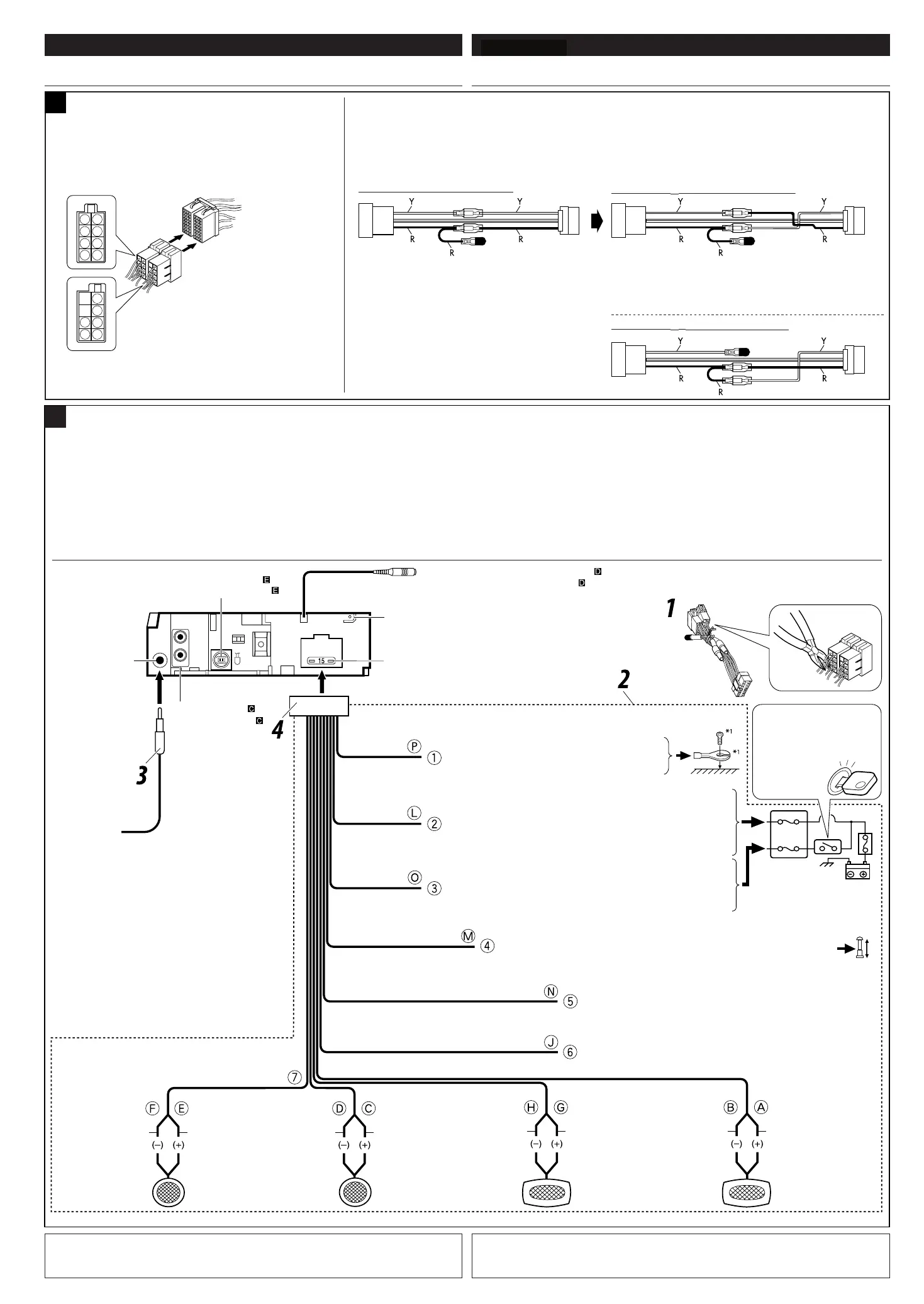
ELECTRICAL CONNECTIONS RACCORDEMENTS ELECTRIQUES
B
Before connecting: Check the wiring in the vehicle carefully. Incorrect connection may cause serious
damage to this unit.
The leads of the power cord and those of the connector from the car body may be different in color.
1
Cut the ISO connector.
2
Connect the colored leads of the power cord in the order specified in the illustration below.
3
Connect the aerial cord.
4 Finally connect the wiring harness to the unit.
Connections without using the ISO connectors / Connexions sans l’utilisation des connecteurs ISO
Avant de commencer la connexion: Vérifiez attentivement le câblage du véhicule. Une connexion
incorrecte peut endommager sérieusement l’appareil.
Le fil du cordon d’alimentation et ceux des connecteurs du châssis de la voiture peuvent être différents en
couleur.
1 Coupez le connecteur ISO.
2
Connectez les fils colorés du cordon d’alimentation dans l’ordre spécifié sur l’illustration ci-dessous.
3
Connectez le cordon d’antenne.
4
Finalement, connectez le faisceau de fils à l’appareil.
E
F
B
D
H
G
A
C
N
J
I
K
M
L
P
O
A
If your car is equipped with the ISO
connector / Si votre voiture est équippée
d’un connecteur ISO
• Connect the ISO connectors as illustrated.
• Connectez les connecteurs ISO comme montré sur l’illustration.
From the car body
De la carrosserie de la
voiture
ISO connector of the supplied power cord
Connecteur ISO pour le cordon d’alimentation
fourni
View from the lead side
Vue à partir du côté des fils
For some VW/Audi or Opel (Vauxhall) automobile / Pour certaine voiture VW/Audi ou Opel
(Vauxhall)
You may need to modify the wiring of the supplied power cord as illustrated.
• Contact your authorized car dealer before installing this unit.
Vous aurrez peut-être besoin de modifier le câblage du cordon d’alimentation fourni comme montré sur l’illustration.
• Contactez votre revendeur automobile autorisé avant d’installer l’appareil.
Original wiring / Câblage original
Modified wiring 1 / Câblage modifié 1
Use modified wiring 2 if the unit does not turn on.
Utilisez le câblage modifié 2 si l’appareil ne se met pas sous tension.
ISO connector
Connecteur ISO
Y: Yellow
Jaune
R: Red
Rouge
Modified wiring 2 / Câblage modifié 2
To external components (see diagram
)
Aux appareíls extérieurs (voir le diagramme
)
Orange with white stripe
Orange avec bande blanche
To car light control switch
À l’interrupteur d’éclairage de la voiture
CONEXIUNI ELECTRICE
ROMÂNĂ
Pentru unele autovehicule VW/Audi sau Opel
(Vauxhall)
• Legaţi conectorii ISO ca în imagine.
Dacă autovehiculul este dotat cu
un conector ISO
De la caroserie
Conectorul ISO al cablului de alimentare
furnizat
Detaliu al conectorului
Instalaţie electrică originală
Conector ISO
Galben Roşu
Instalaţie electrică modificată
3
Line out (see diagram )
Sortie de ligne
(voir le diagramme )
Rear ground terminal
Borne arrière de masse
15 A fuse
Fusible 15 A
Black
Noir
Blue with white stripe
Bleu avec bande blanche
Red
Rouge
Yellow
*
2
Jaune
*
2
Brown
Marron
To metallic body or chassis of the car
Vers corps métallique ou châssis de la voiture
Ignition switch
Interrupteur d’allumage
Fuse block
Porte-fusible
To an accessory terminal in the fuse block
Vers borne accessoire du porte-fusible
To the remote lead of other equipment or power aerial if any (200 mA max.)
Au fil de télécommande de l’autre appareil ou à l’antenne automatique s’il y en a une
(200 mA max.)
To cellular phone system
À un système de téléphone cellulaire
Left speaker (front)
Enceinte gauche (avant)
Right speaker (front)
Enceinte droit (avant)
Left speaker (rear)
Enceinte gauche (arrière)
Right speaker (rear)
Enceinte droit (arrière)
Purple
Violet
Purple with black stripe
Violet avec bande noire
Green
Vert
Green with black stripe
Vert avec bande noire
Gray
Gris
Gray with black stripe
Gris avec bande noire
White
Blanc
White with black stripe
Blanc avec bande noire
To a live terminal in the fuse block connecting to the car battery (bypassing
the ignition switch) (constant 12 V)
À une borne sous tension du porte-fusible connectée à la batterie de la voiture
(en dérivant l’interrupteur d’allumage) (12 V constant)
To steering wheel remote controller (see diagram
)
Pour la télécommande de volant (voir le diagramme
)
Aerial terminal
Borne de l’antenne
*
1
Not supplied for this unit.
*
2
Before checking the operation of this unit prior to installation, this lead must be connected, otherwise power
cannot be turned on.
*
1
Non fourni avec cet autoradio.
*
2
Pour vérifier le fonctionnement de cet appareil avant installation, ce fil doit être raccordé, sinon l’appareil ne peut
pas être mis sous tension.
ENGLISH FRANÇAIS
ELECTRICAL CONNECTIONS RACCORDEMENTS ELECTRIQUES
B
Before connecting: Check the wiring in the vehicle carefully. Incorrect connection may cause serious
damage to this unit.
The leads of the power cord and those of the connector from the car body may be different in color.
1
Cut the ISO connector.
2 Connect the colored leads of the power cord in the order specified in the illustration below.
3
Connect the aerial cord.
4 Finally connect the wiring harness to the unit.
Connections without using the ISO connectors / Connexions sans l’utilisation des connecteurs ISO
Avant de commencer la connexion: Vérifiez attentivement le câblage du véhicule. Une connexion
incorrecte peut endommager sérieusement l’appareil.
Le fil du cordon d’alimentation et ceux des connecteurs du châssis de la voiture peuvent être différents en
couleur.
1 Coupez le connecteur ISO.
2
Connectez les fils colorés du cordon d’alimentation dans l’ordre spécifié sur l’illustration ci-dessous.
3 Connectez le cordon d’antenne.
4
Finalement, connectez le faisceau de fils à l’appareil.
E
F
B
D
H
G
A
C
N
J
I
K
M
L
P
O
A
If your car is equipped with the ISO
connector / Si votre voiture est équippée
d’un connecteur ISO
• Connect the ISO connectors as illustrated.
• Connectez les connecteurs ISO comme montré sur l’illustration.
From the car body
De la carrosserie de la
voiture
ISO connector of the supplied power cord
Connecteur ISO pour le cordon d’alimentation
fourni
View from the lead side
Vue à partir du côté des fils
For some VW/Audi or Opel (Vauxhall) automobile / Pour certaine voiture VW/Audi ou Opel
(Vauxhall)
You may need to modify the wiring of the supplied power cord as illustrated.
• Contact your authorized car dealer before installing this unit.
Vous aurrez peut-être besoin de modifier le câblage du cordon d’alimentation fourni comme montré sur l’illustration.
• Contactez votre revendeur automobile autorisé avant d’installer l’appareil.
Original wiring / Câblage original
Modified wiring 1 / Câblage modifié 1
Use modified wiring 2 if the unit does not turn on.
Utilisez le câblage modifié 2 si l’appareil ne se met pas sous tension.
ISO connector
Connecteur ISO
Y: Yellow
Jaune
R: Red
Rouge
Modified wiring 2 / Câblage modifié 2
To external components (see diagram
)
Aux appareils extérieurs (voir le diagramme
)
Instalaţie electrică modificată
3
Line out (see diagram )
Sortie de ligne
(voir le diagramme )
Rear ground terminal
Borne arrière de masse
15 A fuse
Fusible 15 A
Black
Noir
Blue with white stripe
Bleu avec bande blanche
Red
Rouge
Yellow
*
2
Jaune *
2
Brown
Marron
To metallic body or chassis of the car
Vers corps métallique ou châssis de la voiture
Ignition switch
Interrupteur d’allumage
Fuse block
Porte-fusible
To an accessory terminal in the fuse block
Vers borne accessoire du porte-fusible
To the remote lead of other equipment or power aerial if any (200 mA max.)
Au fil de télécommande de l’autre appareil ou à l’antenne automatique s’il y en a une
(200 mA max.)
To cellular phone system
À un système de téléphone cellulaire
Left speaker (front)
Enceinte gauche (avant)
Right speaker (front)
Enceinte droit (avant)
Left speaker (rear)
Enceinte gauche (arrière)
Right speaker (rear)
Enceinte droit (arrière)
Purple
Violet
Purple with black stripe
Violet avec bande noire
Green
Vert
Green with black stripe
Vert avec bande noire
Gray
Gris
Gray with black stripe
Gris avec bande noire
White
Blanc
White with black stripe
Blanc avec bande noire
To a live terminal in the fuse block connecting to the car battery (bypassing
the ignition switch) (constant 12 V)
À une borne sous tension du porte-fusible connectée à la batterie de la voiture
(en dérivant l’interrupteur d’allumage) (12 V constant)
To steering wheel remote controller (see diagram
)
Pour la télécommande de volant (voir le diagramme
)
Aerial terminal
Borne de l’antenne
*
1
Not supplied for this unit.
*
2
Before checking the operation of this unit prior to installation, this lead must be connected, otherwise power
cannot be turned on.
*
1
Non fourni avec cet autoradio.
*
2
Pour vérifier le fonctionnement de cet appareil avant installation, ce fil doit être raccordé, sinon l’appareil ne peut
pas être mis sous tension.
ENGLISH FRANÇAIS
ELECTRICAL CONNECTIONS RACCORDEMENTS ELECTRIQUES
B
Before connecting: Check the wiring in the vehicle carefully. Incorrect connection may cause serious
damage to this unit.
The leads of the power cord and those of the connector from the car body may be different in color.
1
Cut the ISO connector.
2 Connect the colored leads of the power cord in the order specified in the illustration below.
3 Connect the aerial cord.
4 Finally connect the wiring harness to the unit.
Connections without using the ISO connectors / Connexions sans l’utilisation des connecteurs ISO
Avant de commencer la connexion: Vérifiez attentivement le câblage du véhicule. Une connexion
incorrecte peut endommager sérieusement l’appareil.
Le fil du cordon d’alimentation et ceux des connecteurs du châssis de la voiture peuvent être différents en
couleur.
1 Coupez le connecteur ISO.
2
Connectez les fils colorés du cordon d’alimentation dans l’ordre spécifié sur l’illustration ci-dessous.
3 Connectez le cordon d’antenne.
4
Finalement, connectez le faisceau de fils à l’appareil.
E
F
B
D
H
G
A
C
N
J
I
K
M
L
P
O
A
If your car is equipped with the ISO
connector / Si votre voiture est équippée
d’un connecteur ISO
• Connect the ISO connectors as illustrated.
• Connectez les connecteurs ISO comme montré sur l’illustration.
From the car body
De la carrosserie de la
voiture
ISO connector of the supplied power cord
Connecteur ISO pour le cordon d’alimentation
fourni
View from the lead side
Vue à partir du côté des fils
For some VW/Audi or Opel (Vauxhall) automobile / Pour certaine voiture VW/Audi ou Opel
(Vauxhall)
You may need to modify the wiring of the supplied power cord as illustrated.
• Contact your authorized car dealer before installing this unit.
Vous aurrez peut-être besoin de modifier le câblage du cordon d’alimentation fourni comme montré sur l’illustration.
• Contactez votre revendeur automobile autorisé avant d’installer l’appareil.
Original wiring / Câblage original
Modified wiring 1 / Câblage modifié 1
Use modified wiring 2 if the unit does not turn on.
Utilisez le câblage modifié 2 si l’appareil ne se met pas sous tension.
ISO connector
Connecteur ISO
Y: Yellow
Jaune
R: Red
Rouge
Modified wiring 2 / Câblage modifié 2
To external components (see diagram
)
Aux appareils extérieurs (voir le diagramme
)
Conexiuni realizate fără utilizarea conectorilor ISO
Înainte de conectare: verificaţi cu atenţie instalaţia electrică din autovehicul. Realizarea incorectă a
conexiunii poate duce la deteriorarea gravă a acestui aparat.
Firele cablului de alimentare şi cele ale conectorului montat pe maşină pot avea culori diferite.
1 Întrerupeţi legătura conectorului ISO.
2 Conectaţi firele colorate ale cablului de alimentare în ordinea indicată în imaginea de mai jos.
3 Conectaţi antena.
4 La final, conectaţi cablurile la aparat.
Poate fi necesară modificarea conexiunilor cablului de alimentare furnizat, conform imaginii.
• Înainte de a instala acest aparat, contactaţi dealerul autorizat de la care aţi achiziţionat autovehiculul.
Utilizaţi instalaţia modificată
3
Line out (see diagram )
Sortie de ligne
(voir le diagramme )
Rear ground terminal
Borne arrière de masse
15 A fuse
Fusible 15 A
Black
Noir
Blue with white stripe
Bleu avec bande blanche
Red
Rouge
Yellow
*
2
Jaune
*
2
Brown
Marron
To metallic body or chassis of the car
Vers corps métallique ou châssis de la voiture
Ignition switch
Interrupteur d’allumage
Fuse block
Porte-fusible
To an accessory terminal in the fuse block
Vers borne accessoire du porte-fusible
To the remote lead of other equipment or power aerial if any (200 mA max.)
Au fil de télécommande de l’autre appareil ou à l’antenne automatique s’il y en a une
(200 mA max.)
To cellular phone system
À un système de téléphone cellulaire
Left speaker (front)
Enceinte gauche (avant)
Right speaker (front)
Enceinte droit (avant)
Left speaker (rear)
Enceinte gauche (arrière)
Right speaker (rear)
Enceinte droit (arrière)
Purple
Violet
Purple with black stripe
Violet avec bande noire
Green
Vert
Green with black stripe
Vert avec bande noire
Gray
Gris
Gray with black stripe
Gris avec bande noire
White
Blanc
White with black stripe
Blanc avec bande noire
To a live terminal in the fuse block connecting to the car battery (bypassing
the ignition switch) (constant 12 V)
À une borne sous tension du porte-fusible connectée à la batterie de la voiture
(en dérivant l’interrupteur d’allumage) (12 V constant)
To steering wheel remote controller (see diagram
)
Pour la télécommande de volant (voir le diagramme
)
Aerial terminal
Borne de l’antenne
*
1
Not supplied for this unit.
*
2
Before checking the operation of this unit prior to installation, this lead must be connected, otherwise power
cannot be turned on.
*
1
Non fourni avec cet autoradio.
*
2
Pour vérifier le fonctionnement de cet appareil avant installation, ce fil doit être raccordé, sinon l’appareil ne peut
pas être mis sous tension.
ENGLISH FRANÇAIS
ELECTRICAL CONNECTIONS RACCORDEMENTS ELECTRIQUES
B
Before connecting: Check the wiring in the vehicle carefully. Incorrect connection may cause serious
damage to this unit.
The leads of the power cord and those of the connector from the car body may be different in color.
1
Cut the ISO connector.
2 Connect the colored leads of the power cord in the order specified in the illustration below.
3
Connect the aerial cord.
4 Finally connect the wiring harness to the unit.
Connections without using the ISO connectors / Connexions sans l’utilisation des connecteurs ISO
Avant de commencer la connexion: Vérifiez attentivement le câblage du véhicule. Une connexion
incorrecte peut endommager sérieusement l’appareil.
Le fil du cordon d’alimentation et ceux des connecteurs du châssis de la voiture peuvent être différents en
couleur.
1 Coupez le connecteur ISO.
2
Connectez les fils colorés du cordon d’alimentation dans l’ordre spécifié sur l’illustration ci-dessous.
3 Connectez le cordon d’antenne.
4
Finalement, connectez le faisceau de fils à l’appareil.
E
F
B
D
H
G
A
C
N
J
I
K
M
L
P
O
A
If your car is equipped with the ISO
connector / Si votre voiture est équippée
d’un connecteur ISO
• Connect the ISO connectors as illustrated.
• Connectez les connecteurs ISO comme montré sur l’illustration.
From the car body
De la carrosserie de la
voiture
ISO connector of the supplied power cord
Connecteur ISO pour le cordon d’alimentation
fourni
View from the lead side
Vue à partir du côté des fils
For some VW/Audi or Opel (Vauxhall) automobile / Pour certaine voiture VW/Audi ou Opel
(Vauxhall)
You may need to modify the wiring of the supplied power cord as illustrated.
• Contact your authorized car dealer before installing this unit.
Vous aurrez peut-être besoin de modifier le câblage du cordon d’alimentation fourni comme montré sur l’illustration.
• Contactez votre revendeur automobile autorisé avant d’installer l’appareil.
Original wiring / Câblage original
Modified wiring 1 / Câblage modifié 1
Use modified wiring 2 if the unit does not turn on.
Utilisez le câblage modifié 2 si l’appareil ne se met pas sous tension.
ISO connector
Connecteur ISO
Y: Yellow
Jaune
R: Red
Rouge
Modified wiring 2 / Câblage modifié 2
To external components (see diagram
)
Aux appareils extérieurs (voir le diagramme
)
dacă aparatul nu începe să funcţioneze.
Către telecomanda pentru volan (vezi schema
3
Line out (see diagram )
Sortie de ligne
(voir le diagramme )
Rear ground terminal
Borne arrière de masse
15 A fuse
Fusible 15 A
Black
Noir
Blue with white stripe
Bleu avec bande blanche
Red
Rouge
Yellow
*
2
Jaune *
2
Brown
Marron
To metallic body or chassis of the car
Vers corps métallique ou châssis de la voiture
Ignition switch
Interrupteur d’allumage
Fuse block
Porte-fusible
To an accessory terminal in the fuse block
Vers borne accessoire du porte-fusible
To the remote lead of other equipment or power aerial if any (200 mA max.)
Au fil de télécommande de l’autre appareil ou à l’antenne automatique s’il y en a une
(200 mA max.)
To cellular phone system
À un système de téléphone cellulaire
Left speaker (front)
Enceinte gauche (avant)
Right speaker (front)
Enceinte droit (avant)
Left speaker (rear)
Enceinte gauche (arrière)
Right speaker (rear)
Enceinte droit (arrière)
Purple
Violet
Purple with black stripe
Violet avec bande noire
Green
Vert
Green with black stripe
Vert avec bande noire
Gray
Gris
Gray with black stripe
Gris avec bande noire
White
Blanc
White with black stripe
Blanc avec bande noire
To a live terminal in the fuse block connecting to the car battery (bypassing
the ignition switch) (constant 12 V)
À une borne sous tension du porte-fusible connectée à la batterie de la voiture
(en dérivant l’interrupteur d’allumage) (12 V constant)
To steering wheel remote controller (see diagram
)
Pour la télécommande de volant (voir le diagramme
)
Aerial terminal
Borne de l’antenne
*
1
Not supplied for this unit.
*
2
Before checking the operation of this unit prior to installation, this lead must be connected, otherwise power
cannot be turned on.
*
1
Non fourni avec cet autoradio.
*
2
Pour vérifier le fonctionnement de cet appareil avant installation, ce fil doit être raccordé, sinon l’appareil ne peut
pas être mis sous tension.
ENGLISH FRANÇAIS
ELECTRICAL CONNECTIONS RACCORDEMENTS ELECTRIQUES
B
Before connecting: Check the wiring in the vehicle carefully. Incorrect connection may cause serious
damage to this unit.
The leads of the power cord and those of the connector from the car body may be different in color.
1
Cut the ISO connector.
2 Connect the colored leads of the power cord in the order specified in the illustration below.
3 Connect the aerial cord.
4 Finally connect the wiring harness to the unit.
Connections without using the ISO connectors / Connexions sans l’utilisation des connecteurs ISO
Avant de commencer la connexion: Vérifiez attentivement le câblage du véhicule. Une connexion
incorrecte peut endommager sérieusement l’appareil.
Le fil du cordon d’alimentation et ceux des connecteurs du châssis de la voiture peuvent être différents en
couleur.
1 Coupez le connecteur ISO.
2
Connectez les fils colorés du cordon d’alimentation dans l’ordre spécifié sur l’illustration ci-dessous.
3 Connectez le cordon d’antenne.
4
Finalement, connectez le faisceau de fils à l’appareil.
E
F
B
D
H
G
A
C
N
J
I
K
M
L
P
O
A
If your car is equipped with the ISO
connector / Si votre voiture est équippée
d’un connecteur ISO
• Connect the ISO connectors as illustrated.
• Connectez les connecteurs ISO comme montré sur l’illustration.
From the car body
De la carrosserie de la
voiture
ISO connector of the supplied power cord
Connecteur ISO pour le cordon d’alimentation
fourni
View from the lead side
Vue à partir du côté des fils
For some VW/Audi or Opel (Vauxhall) automobile / Pour certaine voiture VW/Audi ou Opel
(Vauxhall)
You may need to modify the wiring of the supplied power cord as illustrated.
• Contact your authorized car dealer before installing this unit.
Vous aurrez peut-être besoin de modifier le câblage du cordon d’alimentation fourni comme montré sur l’illustration.
• Contactez votre revendeur automobile autorisé avant d’installer l’appareil.
Original wiring / Câblage original
Modified wiring 1 / Câblage modifié 1
Use modified wiring 2 if the unit does not turn on.
Utilisez le câblage modifié 2 si l’appareil ne se met pas sous tension.
ISO connector
Connecteur ISO
Y: Yellow
Jaune
R: Red
Rouge
Modified wiring 2 / Câblage modifié 2
To external components (see diagram
)
Aux appareils extérieurs (voir le diagramme
)
)
Borna antenei
Mufă ieşire (vezi schema
3
Line out (see diagram )
Sortie de ligne
(voir le diagramme )
Rear ground terminal
Borne arrière de masse
15 A fuse
Fusible 15 A
Black
Noir
Blue with white stripe
Bleu avec bande blanche
Red
Rouge
Yellow
*
2
Jaune
*
2
Brown
Marron
To metallic body or chassis of the car
Vers corps métallique ou châssis de la voiture
Ignition switch
Interrupteur d’allumage
Fuse block
Porte-fusible
To an accessory terminal in the fuse block
Vers borne accessoire du porte-fusible
To the remote lead of other equipment or power aerial if any (200 mA max.)
Au fil de télécommande de l’autre appareil ou à l’antenne automatique s’il y en a une
(200 mA max.)
To cellular phone system
À un système de téléphone cellulaire
Left speaker (front)
Enceinte gauche (avant)
Right speaker (front)
Enceinte droit (avant)
Left speaker (rear)
Enceinte gauche (arrière)
Right speaker (rear)
Enceinte droit (arrière)
Purple
Violet
Purple with black stripe
Violet avec bande noire
Green
Vert
Green with black stripe
Vert avec bande noire
Gray
Gris
Gray with black stripe
Gris avec bande noire
White
Blanc
White with black stripe
Blanc avec bande noire
To a live terminal in the fuse block connecting to the car battery (bypassing
the ignition switch) (constant 12 V)
À une borne sous tension du porte-fusible connectée à la batterie de la voiture
(en dérivant l’interrupteur d’allumage) (12 V constant)
To steering wheel remote controller (see diagram
)
Pour la télécommande de volant (voir le diagramme
)
Aerial terminal
Borne de l’antenne
*
1
Not supplied for this unit.
*
2
Before checking the operation of this unit prior to installation, this lead must be connected, otherwise power
cannot be turned on.
*
1
Non fourni avec cet autoradio.
*
2
Pour vérifier le fonctionnement de cet appareil avant installation, ce fil doit être raccordé, sinon l’appareil ne peut
pas être mis sous tension.
ENGLISH FRANÇAIS
ELECTRICAL CONNECTIONS RACCORDEMENTS ELECTRIQUES
B
Before connecting: Check the wiring in the vehicle carefully. Incorrect connection may cause serious
damage to this unit.
The leads of the power cord and those of the connector from the car body may be different in color.
1
Cut the ISO connector.
2 Connect the colored leads of the power cord in the order specified in the illustration below.
3
Connect the aerial cord.
4 Finally connect the wiring harness to the unit.
Connections without using the ISO connectors / Connexions sans l’utilisation des connecteurs ISO
Avant de commencer la connexion: Vérifiez attentivement le câblage du véhicule. Une connexion
incorrecte peut endommager sérieusement l’appareil.
Le fil du cordon d’alimentation et ceux des connecteurs du châssis de la voiture peuvent être différents en
couleur.
1 Coupez le connecteur ISO.
2
Connectez les fils colorés du cordon d’alimentation dans l’ordre spécifié sur l’illustration ci-dessous.
3 Connectez le cordon d’antenne.
4
Finalement, connectez le faisceau de fils à l’appareil.
E
F
B
D
H
G
A
C
N
J
I
K
M
L
P
O
A
If your car is equipped with the ISO
connector / Si votre voiture est équippée
d’un connecteur ISO
• Connect the ISO connectors as illustrated.
• Connectez les connecteurs ISO comme montré sur l’illustration.
From the car body
De la carrosserie de la
voiture
ISO connector of the supplied power cord
Connecteur ISO pour le cordon d’alimentation
fourni
View from the lead side
Vue à partir du côté des fils
For some VW/Audi or Opel (Vauxhall) automobile / Pour certaine voiture VW/Audi ou Opel
(Vauxhall)
You may need to modify the wiring of the supplied power cord as illustrated.
• Contact your authorized car dealer before installing this unit.
Vous aurrez peut-être besoin de modifier le câblage du cordon d’alimentation fourni comme montré sur l’illustration.
• Contactez votre revendeur automobile autorisé avant d’installer l’appareil.
Original wiring / Câblage original
Modified wiring 1 / Câblage modifié 1
Use modified wiring 2 if the unit does not turn on.
Utilisez le câblage modifié 2 si l’appareil ne se met pas sous tension.
ISO connector
Connecteur ISO
Y: Yellow
Jaune
R: Red
Rouge
Modified wiring 2 / Câblage modifié 2
To external components (see diagram
)
Aux appareils extérieurs (voir le diagramme
)
)
Siguranţa 15 A
Negru
Galben
*2
Roşu
Albastru cu dungă albă
Maro
Către caroseria metalică sau şasiul autovehiculului
Către borna sub tensiune a panoului de siguranţe conectată la bateria
autovehiculului (ocolind comutatorul de contact) (12 V constant)
Către o bornă suplimentară situată în panoul de siguranţe
Către firul telecomenzii unui echipament extern sau a antenei automate, în cazul în care
acestea există (maxim 200 mA).
Către comutatorul de lumini al autovehiculului
Comutator de contact
Panoul de siguranţe
Alb cu o dungă neagră Alb Gri cu o dungă neagră Gri Verde cu o dungă neagră Verde Violet cu o dungă neagră Violet
Difuzorul din stânga (faţă)
Difuzorul din dreapta (faţă) Difuzorul din stânga (spate)
Difuzorul din dreapta (spate)
*1
Nu sunt incluse.
*2
Acest fir trebuie conectat înainte de testarea aparatului; în caz contrar, alimentarea electrică nu se
realizează.
Borna de masă spate
Către componentele externe (vezi schema
3
Line out (see diagram )
Sortie de ligne
(voir le diagramme )
Rear ground terminal
Borne arrière de masse
15 A fuse
Fusible 15 A
Black
Noir
Blue with white stripe
Bleu avec bande blanche
Red
Rouge
Yellow *
2
Jaune
*
2
Brown
Marron
To metallic body or chassis of the car
Vers corps métallique ou châssis de la voiture
Ignition switch
Interrupteur d’allumage
Fuse block
Porte-fusible
To an accessory terminal in the fuse block
Vers borne accessoire du porte-fusible
To the remote lead of other equipment or power aerial if any (200 mA max.)
Au fil de télécommande de l’autre appareil ou à l’antenne automatique s’il y en a une
(200 mA max.)
To cellular phone system
À un système de téléphone cellulaire
Left speaker (front)
Enceinte gauche (avant)
Right speaker (front)
Enceinte droit (avant)
Left speaker (rear)
Enceinte gauche (arrière)
Right speaker (rear)
Enceinte droit (arrière)
Purple
Violet
Purple with black stripe
Violet avec bande noire
Green
Vert
Green with black stripe
Vert avec bande noire
Gray
Gris
Gray with black stripe
Gris avec bande noire
White
Blanc
White with black stripe
Blanc avec bande noire
To a live terminal in the fuse block connecting to the car battery (bypassing
the ignition switch) (constant 12 V)
À une borne sous tension du porte-fusible connectée à la batterie de la voiture
(en dérivant l’interrupteur d’allumage) (12 V constant)
To steering wheel remote controller (see diagram )
Pour la télécommande de volant (voir le diagramme
)
Aerial terminal
Borne de l’antenne
*
1
Not supplied for this unit.
*
2
Before checking the operation of this unit prior to installation, this lead must be connected, otherwise power
cannot be turned on.
*
1
Non fourni avec cet autoradio.
*
2
Pour vérifier le fonctionnement de cet appareil avant installation, ce fil doit être raccordé, sinon l’appareil ne peut
pas être mis sous tension.
ENGLISH FRANÇAIS
ELECTRICAL CONNECTIONS RACCORDEMENTS ELECTRIQUES
B
Before connecting: Check the wiring in the vehicle carefully. Incorrect connection may cause serious
damage to this unit.
The leads of the power cord and those of the connector from the car body may be different in color.
1
Cut the ISO connector.
2 Connect the colored leads of the power cord in the order specified in the illustration below.
3 Connect the aerial cord.
4 Finally connect the wiring harness to the unit.
Connections without using the ISO connectors / Connexions sans l’utilisation des connecteurs ISO
Avant de commencer la connexion: Vérifiez attentivement le câblage du véhicule. Une connexion
incorrecte peut endommager sérieusement l’appareil.
Le fil du cordon d’alimentation et ceux des connecteurs du châssis de la voiture peuvent être différents en
couleur.
1 Coupez le connecteur ISO.
2
Connectez les fils colorés du cordon d’alimentation dans l’ordre spécifié sur l’illustration ci-dessous.
3 Connectez le cordon d’antenne.
4
Finalement, connectez le faisceau de fils à l’appareil.
E
F
B
D
H
G
A
C
N
J
I
K
M
L
P
O
A
If your car is equipped with the ISO
connector / Si votre voiture est équippée
d’un connecteur ISO
• Connect the ISO connectors as illustrated.
• Connectez les connecteurs ISO comme montré sur l’illustration.
From the car body
De la carrosserie de la
voiture
ISO connector of the supplied power cord
Connecteur ISO pour le cordon d’alimentation
fourni
View from the lead side
Vue à partir du côté des fils
For some VW/Audi or Opel (Vauxhall) automobile / Pour certaine voiture VW/Audi ou Opel
(Vauxhall)
You may need to modify the wiring of the supplied power cord as illustrated.
• Contact your authorized car dealer before installing this unit.
Vous aurrez peut-être besoin de modifier le câblage du cordon d’alimentation fourni comme montré sur l’illustration.
• Contactez votre revendeur automobile autorisé avant d’installer l’appareil.
Original wiring / Câblage original
Modified wiring 1 / Câblage modifié 1
Use modified wiring 2 if the unit does not turn on.
Utilisez le câblage modifié 2 si l’appareil ne se met pas sous tension.
ISO connector
Connecteur ISO
Y: Yellow
Jaune
R: Red
Rouge
Modified wiring 2 / Câblage modifié 2
To external components (see diagram
)
Aux appareíls extérieurs (voir le diagramme
)
Orange with white stripe
Orange avec bande blanche
To car light control switch
À l’interrupteur d’éclairage de la voiture
)
Portocaliu cu o dungă albă
Către sistemul telefonului celular
(ILUMINARE)
 Loading...