(No.MA665<Rev.001>)10/33
109 Vcc - Power supply
110 MDATA O Microcontroller Command Data Signal
111 TU_RST O HELIO/CAYMAN (HD) Reset L: Reset ON / H: Reset OFF
111 NC O No Use (For non DAB/HD model)
112 PVcc - Power supply for I/O circuits
113 SXM_PWR O Power Supply for SXM (For SXM model only) L: PWR Off / H: PWR On
113 NC O No Use (for non SXM model)
114 Vss - GND
115 DRV_CNT O Loading Motor Control Output
116 BEEP O Output for Beep Tone Generator H (Pulse): BEEP / L: OFF
117 DRV_Lo/Ej O Loading Motor Control Output
118 PCB_TEST_MODE I PCB Test Mode Switch L: Normal Mode / H: Check Mode
(After Reset software need to
check the pin input. If detect high it
should enter Serial Number mode)
118 WDT O Watch Dog Timer output L: Normal Mode / H: Reset by WDT
119 SW2 I CD Mecha SW2
119 DEBUG_2B O For Debug
119 Field Test 2 O RDS data log output (standby for field test)
120 BLKCK I Sub-Code Block Clock Signal
120 Field Test 1 O RDS data log output (standby for field test)
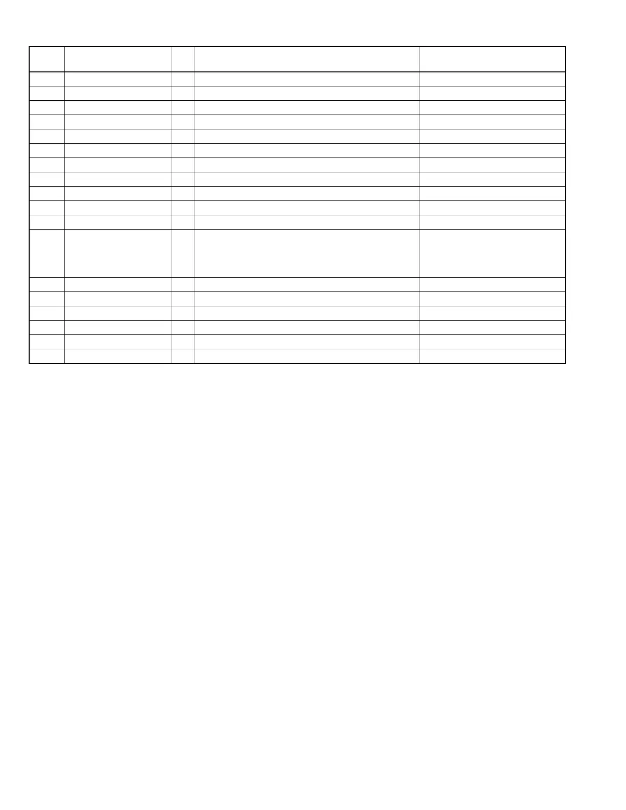
Pin No. Pin Name I/O Application
Processing/Operation/Descrip-
tion
 Loading...