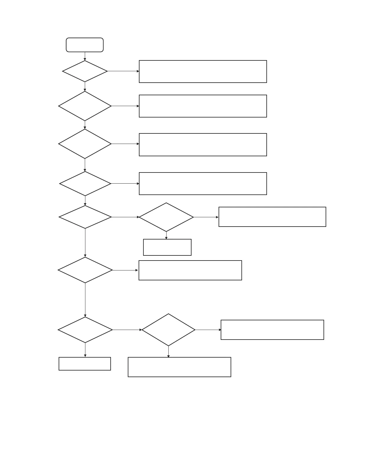
10A Fuse
No Power
YES
NO
D861/ R1080
Open?
YES
IC901
(BU_DET)
YES
NO
NO
IC901 Pin15
3.3V?
YES
YES
YES
NO
IC891 Pin6
5.2V?
NO
NO
IC901
(ACC_DET)
YES
IC891 Pin3
3.3V?
Check R705 Open
Replace New 10A Fuse
Check pattern and component between
CN990 Pin13 to IC901 Pin6.
IC901 Pin 7 & 8 supply must keep above 7.5V,
Check D903, D902, C919 & C918.
Replace Component
NO
NO
IC851 Pin5
1.2V?
Re-program ROM Check the component connected to
IC901 Pin11, maybe shorted.
Check the component connected to
IC901 Pin15, maybe shorted.
Check the component connected to
IC851, maybe shorted.
IC851 Pin1 /
Pin3 3.3V?
Short Circuit
NO
YES
YES
IC891 Output
 Loading...