(No.MA665<Rev.001>)12/33
3.1.3 Removing the SWITCH PWB (See Fig.5)
(1) Remove the 3 screws.
(2) Disengage the 15 hooks, and remove the REAR COVER.
(3) Remove the SWITCH PWB.
Fig.5
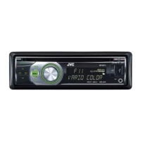
3.2 CD mechanism
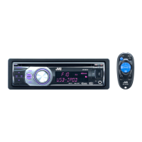
• NOTICE FOR HANDRIG OF MECHANISM ASSY
• THESE PARTS NEED CAUTION OF HANDLING
CAUTION:
Don't touch the following parts in particular by the hand which
touched grease. (It becomes a cause of traction problem)
REAR COVER
SWITCH PWB
CAUTION PARTS
HC TURN TABLE TRIGGER ARM
ROLLER DISC GUIDE
OK
Handle CHASSIS part.
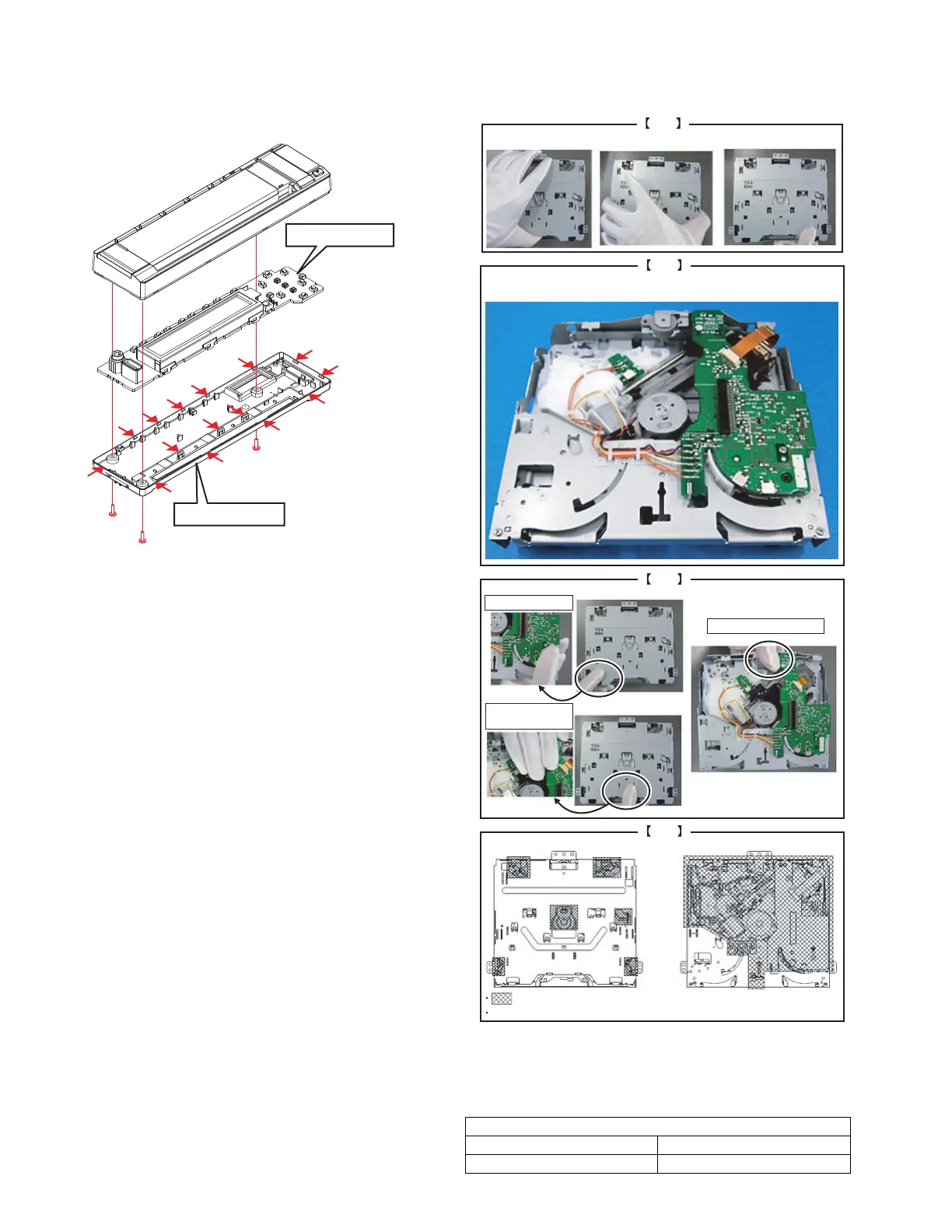
NG
Do not stay MECHANISM ASSY in upside-down condition
for 1 hour and more.
NG
Do not touch DAMPER.
Do not touch P.C.B..
Do not touch
PICK UP ASSY.
DO NOT TOUCH HOLES, MOTOR, DAMPER, PCB, FFC, OPU AND WIRE.
DO NOT TOUCH AREA
TOP SIDE BOTTOM SIDE
NG
 Loading...