KD-S895
(No.49798)1-5
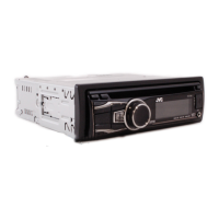
2.1.3 Removing the heat sink
(See Fig.5)
(1) Remove the two screws B and two screws C on the left
side of the main body.
Fig.5
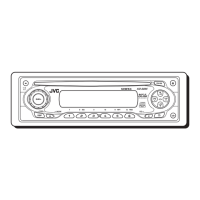
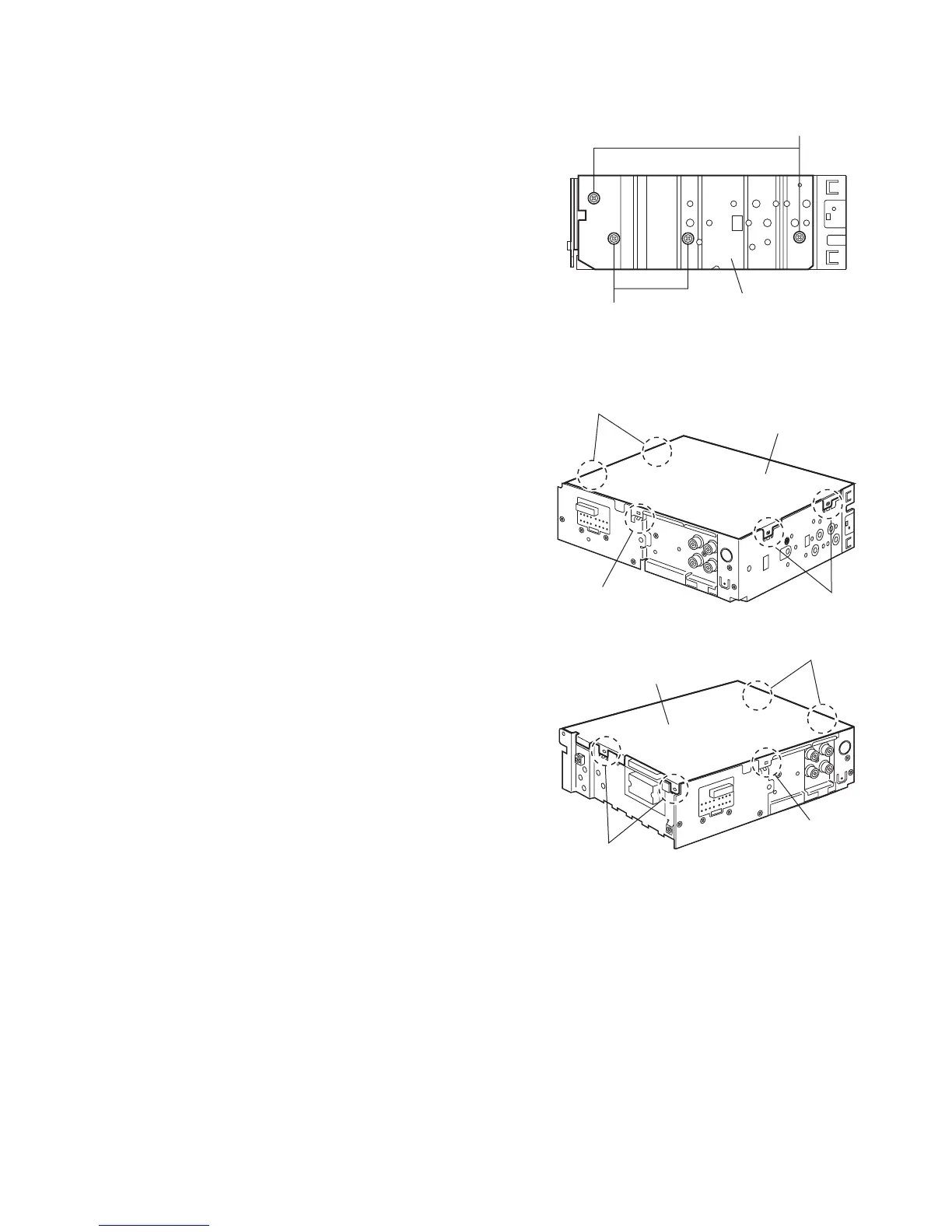
2.1.4 Removing the bottom cover
(See Figs.6 and 7)
• Prior to performing the following procedure, remove the front
panel assembly, front chassis assembly and heat sink.
(1) Turn over the main body, and release the two joints d, two
joints e and joint f.
CAUTION:
Do not damage the main board when releasing the joint f using
a screwdriver. (See Figs.6 and 7)
Fig.6
Fig.7
B
C
Heat sink
Joint
d
Joint e
Joint f
Bottom cover
Joint e
Joint d
Joint f
Bottom cover
 Loading...