KD-SH77R/KD-SH55R
1-8
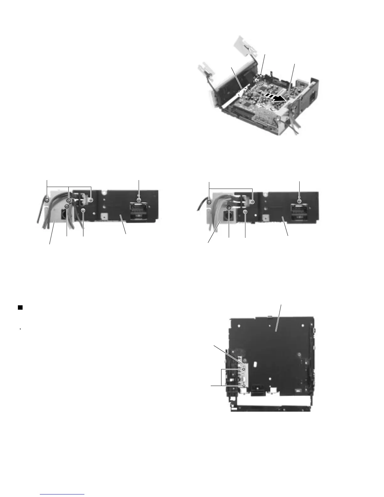
Remove the two screws L and move the main board
backwards to release the two joints a. (The main
board will be removed with the rear panel and the
rear heat sink)
Remove the screw M and N attaching the rear heat
sink.
Remove the two screws O and the screw P
attaching the rear panel. Remove the mainboard
(KD-SH55RE).
Remove the three screws O and the screw P
attaching the rear panel. Remove the main board
(KD-SH77RE).
6.
7.
8.
9.
Prior to performing the following procedures, remove
the top chassis, the motor bracket and the main
board.
Remove the two screws Q attaching the lifter switch
board.
1.
Removing the lifter switch board
(See Fig.16)
Fig.15 (KD-SH55RE)Fig.15 (KD-SH77RE)
Fig.14
Fig.16
Joint a
Joint a
Main board
Rear panel
Rear panel
O
O
M
M
N
N
P
P
Rear heat sink
Rear heat sink
Bottom cover
Lifter switch board
Q

 Loading...