LVT2505-001A_KS-AX204.indd 3LVT2505-001A_KS-AX204.indd 3 9/26/13 1:01 PM9/26/13 1:01 PM
English
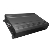
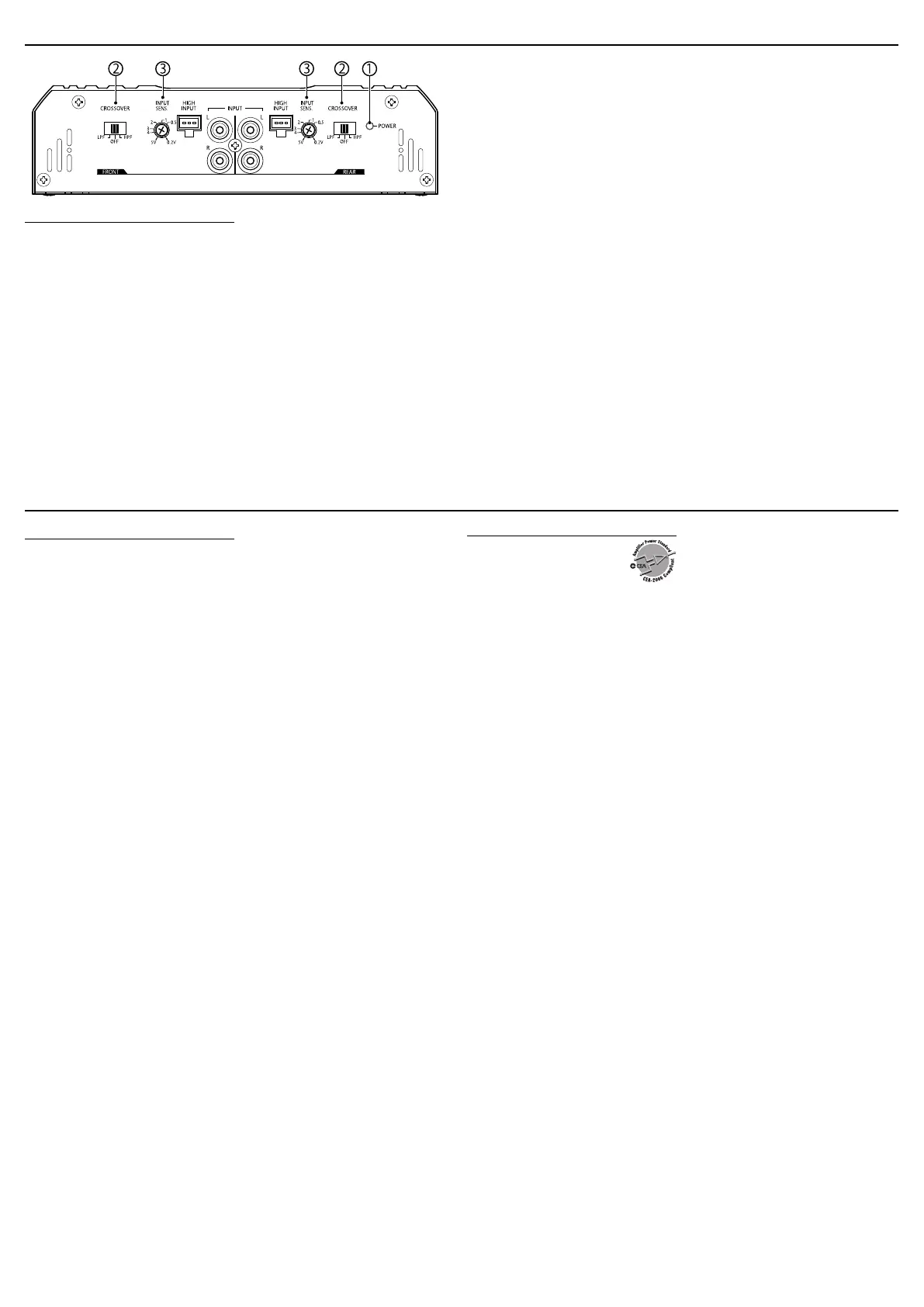
CONTROLS
1
POWER indicator
The green lamp lights while the unit is turned on.
2
CROSSOVER filter switch
OFF:
Normally set to this position.
LPF:
Set to this position when you want to turn on the LPF (Low-Pass
Filter) switch. The Low Pass Filter transmits frequencies lower than
80 Hz.
HPF:
Set to this position when you want to turn on the HPF (High-Pass
Filter) switch. The High-Pass Filter transmits frequencies higher than
150 Hz.
3
INPUT SENS. (input sensitivity) controller
Set this control according to the line-output level of the center
unit connected with this unit. For the line-output level, refer to the
“SPECIFICATIONS” in the instruction manual of the center unit. This
controller is preset to 5 V when the unit is shipped.
CONTROLS
3
English
TROUBLESHOOTING
The POWER indicator does not light.
• Change the fuses if the current one is blown.
• Connect the ground lead securely to a metal part of the car.
• Confirm the battery voltage (11 V to 16 V).
• Leave the unit turned off to cool it down if it heats up abnormally.
No sound is heard.
• Confirm the connections for the power supply. (See “POWER
SUPPLY CONNECTION”.)
• Connect the RCA pin cords to the INPUT jacks, or the speaker input
connector to the HIGH INPUT terminal.
• Confirm the speaker wirings and the position of the CROSSOVER
filter switch. (See “SPEAKER CONNECTIONS”.)
Alternator noise is heard.
• Keep the leads of the POWER terminals away from the RCA pin
cords.
• Keep the RCA pin cords away from other electrical cables in the
car.
• Connect the ground lead securely to a metal part of the car.
• Make sure the speaker negative leads do not touch the car chassis.
• Connect a bypass capacitor across the accessory switches (horn,
fan, etc.).
Noise is made when you connect the unit to an
AM (MW/LW) tuner.
• Move all the leads of this unit away from the antenna (aerial) lead.
TROUBLESHOOTING
English
SPECIFICATIONS
Power Output
Normal Mode: 40 W RMS × 4 channels at 4 Ω and
≤ 1% THD + N
Signal-to-Noise Ratio: 80 dBA (reference: 1 W into 4 Ω)
Power Output
Normal Mode: 60 W RMS × 4 channels at 2 Ω and ≤ 1% THD + N
Bridge Mode: 120 W RMS × 2 channels at 4 Ω and ≤ 1% THD + N
Maximum Power Output
600 W
Load Impedance
Normal Mode: 4 Ω (2 Ω to 8 Ω allowance)
Bridge Mode: 4 Ω (4 Ω to 8 Ω allowance)
Frequency Response
5 Hz to 50,000 Hz ( +0 dB, –3 dB)
Input Sensitivity/Impedance
2 V/21 kΩ (0.2 V to 5 V, variable)
Distortion
Less than 0.06% (at 1 kHz)
Power Requirement
DC 14.4 V (11 V to 16 V allowance)
Grounding system
Negative ground
Dimensions (W×H×D)
300 mm × 49.5 mm × 185 mm
(11-13/16 in. × 2 in. × 7-5/16 in.)
Mass (approx.)
1.9 kg (4.2 lbs)
Accessories
Speaker input connector 3P × 2
Mounting Screw Ø 4 × 20 mm (13/16 in.) × 4
Design and specifications are subject to change without notice.
SPECIFICATIONS
LLVVTT22550055--000011AA__KKSS--AAXX220044..iinndddd 77 99//2266//1133 11::0011 PPMM
Learn more about car amplifiers on our website.
 Loading...