KS-FX621
(No.49825)1-5
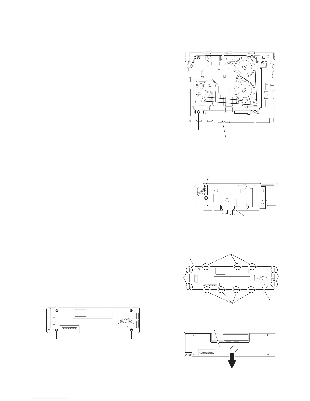
2.1.7 Removing the cassette mechanism assembly
(See Fig.7)
• Prior to performing the following procedure, remove the front
panel assembly, bottom cover, front chassis, heat sink, rear
panel and main board.
(1) Remove the four screws H attaching the cassette mecha-
nism assembly from the top chassis.
Fig.7
2.1.8 Removing the mecha board
(See Fig.8)
• Prior to performing the following procedure, remove the front
panel assembly, bottom cover, front chassis, heat sink, rear
panel, main board and cassette mechanism assembly.
(1) Disconnect the wire from the connectors CN402 and
CN403 on the mecha board.
(2) Remove the screw J attaching the mecha board.
Fig.8
2.1.9 Removing the front board
(See Figs.9 to 11)
• Prior to performing the following procedure, remove the front
panel assembly.
(1) Remove the four screws L attaching the rear cover on the
back of the front panel assembly. (See fig.9)
(2) Release the eleven joints f, the front panel and the rear
cover become separate. (See fig.10)
(3) Remove the front board from the front panel assembly.
(See fig.11)
Fig.9
Fig.10
Fig.11
H
H
H H
Top chassis
Cassette mechanism assembly
J
CN402
CN401
CN403
K
K K
K
Joint h
Joint h
Joint h
Joint h
Front panel assembly
Rear cover
LCD & Key control board