– 1 –
Parts list for installation and connection
The following parts are provided with this unit.
After checking them, please set them correctly.
Installation requires some special knowledge.
Do not install the monitor system yourself. Consult a dealer having special
knowledge of this kind for safe and reliable installation.
KS-JA0502-3
Installation/Connection Manual
LVT2125-004A
[A]
CAUTION
Since there may be legal regulations defining the permissible installation
locations for the color monitor which differ by country or by state, be sure to
install the color monitor in a location complying with any such laws.
0110NSMMDWJEIN
EN
To prevent short circuits, we recommend that you
disconnect the battery’s negative terminal and make
all electrical connections before installing the unit. If
you are not sure how to install this unit correctly, have
it installed by a qualified technician.
Note:
This unit is designed to operate on 12 V DC,
NEGATIVE ground electrical systems. If your
vehicle does not have this system, a voltage inverter
is required, which can be purchased at JVC car audio
dealers.
• Replace the fuse with one of the specified ratings. If
the fuse blows frequently, consult your JVC car audio
dealer.
ELECTRICAL CONNECTIONS
Typical Connections
Before connecting: Check the wiring in the vehicle carefully. Incorrect connection may cause serious
damage to this unit.
The leads of the power cord and the ceiling light cord and those of the connector from the car body may be
different in color.
Connect the colored leads of the power cord in the order specified in the illustration below.
• After connection is finished, connect the power cord to the unit when mounting the unit to the car (see the
reverse page).
*
1
Before checking the operation of this unit prior to
installation, this lead must be connected, otherwise
power cannot be turned on.
*
2
Not included with this unit.
Grey
Red
Yellow*
1
Black*
1
Fuse block
To the door sensor
To metallic body or chassis of the car
To a live terminal in the fuse block connecting to
the car battery (bypassing the ignition switch)
*
2
Power cord
Ignition switch
To an accessory terminal in the fuse block
Orange
To car light control switch
CAUTION:
• To prevent short-circuit, cover the terminals of
the UNUSED leads with insulating tape.
Twist the core
wires when
connecting.
Connecting the leads
Solder the core
wires to connect
them securely.
WARNING
• DO NOT INSTALL THE MONITOR IN A LOCATION WHICH OBSTRUCTS
DRIVING, VISIBILITY OR WHICH IS PROHIBITED BY APPLICABLE LAWS
AND REGULATIONS.
If the monitor is installed in a location which obstructs forward visibility or
operation of the air bag or other safety equipment or which interferes with
operation of the vehicle, it may cause an accident.
• NEVER USE BOLTS OR NUTS FROM THE VEHICLE’S SAFETY DEVICES
FOR INSTALLATION.
If bolts or nuts from the steering wheel, brakes or other safety devices are used
for installation of the monitor, it may cause an accident.
• ATTACH THE WIRES CORRECTLY.
If the wiring is not correctly performed, it may cause a fire or an accident. In
particular, be sure to run and secure the lead wire so that it does not get tangled
with a screw or the moving portion of a seat rail.
• USE WITH DC 12 V NEGATIVE GROUND VEHICLES.
This monitor system is only for use in a DC 12 V negative ground vehicle.
It cannot be used in large trucks or diesel vehicles which are DC 24 V vehicles.
If it is used in the wrong type of vehicle, it may cause a fire or accident.
• To prevent short circuits, we recommend that you disconnect the battery’s
negative terminal and make all electrical connections before installing the unit. If
you are not sure how to install this unit correctly, have it installed by a qualified
technician.
• Avoid installing the monitor connection unit in the following places
– Where it would hinder your safe driving.
– Where it would be exposed to direct sunlight or heat directly from the heater or
placed in an extremely hot place.
– Where it would be subject to rain, water splashes or excessive humidity.
– Where it would be subject to dust.
– Where it would be positioned on an unstable place.
– Where it could damage the car’s fittings.
– Where proper ventilation would not be maintained, such as under a floor mat.
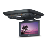
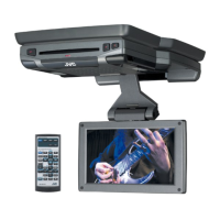
Wide color monitor
Shroud
Paper template
Power cord
Metal plate
Remote controller
Headphones Battery
(for headphones)
Battery
(for remote
controller)
MENU
*
2
Screws
(M5 x 10 mm)
Screws
(M5 x 8 mm)
Nuts (M5)Protection tape
Install_KS-JA0502-3[A].indd 1Install_KS-JA0502-3[A].indd 1 10.1.25 11:03:52 AM10.1.25 11:03:52 AM