*
2
*
2
1
2
3
4
5
6
7
8
3
1
*
1
PA R K I N G
B
RAKE
REVERSE
GEAR
SIGNAL
2
SUBWOOFER
OUT
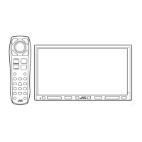
DIRECT STEERING REMOTE
KW-AV70BT
KW-AV70
KW-AV70BT
KW-AV70
KW-AV70BT
KW-AV70BT
KW-AV70
KW-AV70BT
KW-AV70
KW-AV70BT/KW-AV70
KW-AV70BT
KW-AV70
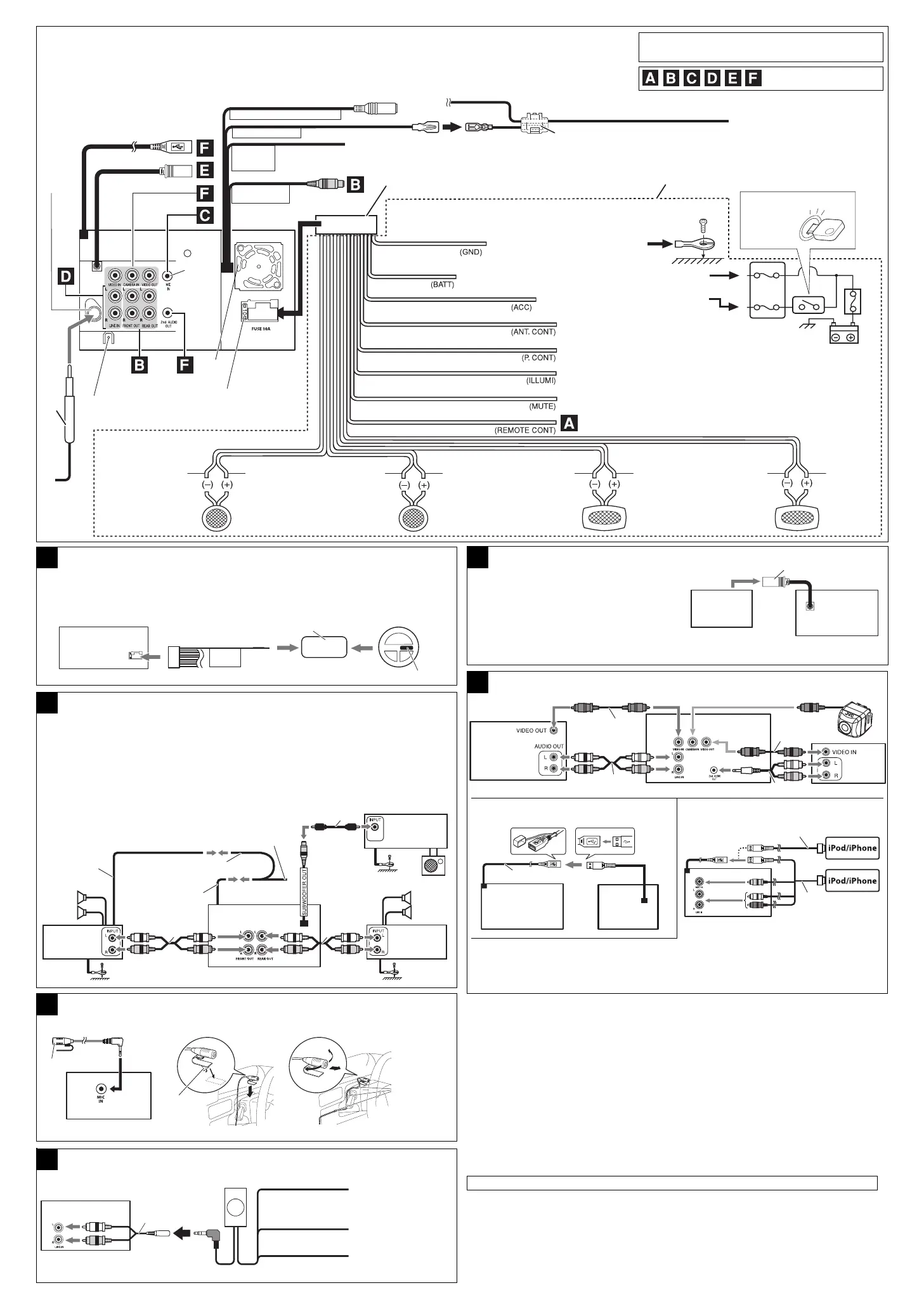
Connecting to the steering wheel remote controller
A
Connecting the external amplifiers and subwoofer
B
Connecting the external components
F
Connecting an external navigation unit
E
Connecting the microphone (Only for KW-AV70BT)
C
1
Before connecting: Check the wiring in the vehicle carefully. Incorrect connection may cause serious damage to this unit.
The leads of the power cord and those of the connector from the car body may be different in color.
1 Connect the colored leads of the power cord in the order specified in the illustration below.
2 Connect the antenna cord.
3 Finally connect the wiring harness to the unit.
See each diagram below.
Black
Yellow *
3
Red
Orange with white stripe
Brown
Light green
Blue with white stripe
Blue
To the OE remote adapter *
4
To metallic body or chassis of the car
To a live terminal in the fuse block connecting to the car battery
(bypassing the ignition switch) (constant 12 V)
To an accessory terminal in the fuse block
To car light control switch
To mobile phone system
To automatic antenna if any (250 mA max.)
To the remote lead of other equipment (200 mA max.)
Crimp connector
White with black stripe White Gray with black stripe Gray Green with black stripe Green Purple with black stripe Purple
Left speaker
(front)
Right speaker
(front)
Left speaker
(rear)
Right speaker
(rear)
10 A fuse
Fan
Rear ground
terminal
Antenna
terminal
If your car is equipped with the steering wheel remote controller, you can operate this unit using the
controller. For connection, an exclusive remote adapter (not supplied) which matches your car is
required. For details, consult the same car audio dealer as where the unit is purchased.
OE remote adapter *
2
*
5
Steering wheel remote controller (equipped in the car)
*
6
*
6
*
6
*
7
*
7
*
7
You can connect an amplifier to upgrade your car stereo system.
• Connect the remote lead (blue with white stripe) to the remote lead of the other equipment so that it
can be controlled through this unit.
• Disconnect the speakers from this unit, and connect them to the amplifier. Leave the
speaker leads of this unit unused.
• You can switch off the built-in amplifier and send the audio signals only to the external amplifier(s) to
get clear sounds and to prevent internal heat built-up inside the unit.
See page 44 of the INSTRUCTIONS.
Subwoofer
JVC
Amplifier
JVC Amplifier
JVC
Amplifier
Remote lead
*
2
Front
speakers
Rear
speakers
To the remote lead of other equipment
Remote lead (blue
with white stripe)
Y-connector
*
2
Camcorder
etc.
External
monitor
KV-CM10 / KV-CM20 *
2
*
9
Rear view camera
USB devices
USB cable (approx. 1 m)
USB device
Connecting the iPod or the iPhone
KS-U30
(not supplied)
USB 2.0 cable (accessory of the iPod/iPhone)
*
1
Only for KW-AV70BT.
*
2
Not supplied for this unit.
*
3
Before checking the operation of this unit prior to installation, this lead must be connected, otherwise power cannot
be turned on. Do not connect the lead directly to the battery.
*
4
Do not connect the lead to any device other than the OE remote adapter. Doing so may cause malfunction.
*
5
Alter the wire of the OE remote adapter to connect to the steering wheel remote lead.
*
6
Audio cord (not supplied for this unit).
*
7
Firmly attach the ground wire to the metallic body or to the chassis of the car—to the place uncoated with paint (if
coated with paint, remove the paint before attaching the wire). Failure to do so may cause damage to the unit.
*
8
Video cord (not supplied for this unit).
*
9
KV-CM10 / KV-CM20 is not sold in some areas. For details, consult your JVC car audio dealer.
*
10
When using the cable, you need to change the setting on the unit (see page 27 of the INSTRUCTIONS).
• iPod and iPhone are trademarks of Apple Inc., registered in the U.S. and other countries.
Connect an external navigation unit to the RGB input
terminal. The positional information detected on the
touch panel and picture signals from the navigation
unit are transferred through the terminal.
Refer to the manual of the external navigation unit for
details.
• Please contact your dealer to inquire about compatible navigation units.
• JVC cannot guarantee proper operation of the external devices connected to the RGB input terminal.
External
navigation
unit *
2
RGB input terminal
Fuse block
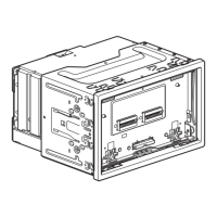
The terminals and cables of all models are shown in the
illustration for the purpose of explanation.
Ignition switch
(See page 1)
To parking brake (see page 1)
Secure the
microphone
cord using cord
cramps (not
supplied) if
necessary.
Microphone
Adhesive
tape
2
3
Blue with yellow stripe
Connecting the Bluetooth adapter (Only for KW-AV70)
D
To the brown lead of the
supplied power cord 7
To the blue with white
stripe lead of the supplied
power cord 5
Ground
Blue with white stripe
Black
Brown
KS-BTA100
*2
See page 59 of the INSTRUCTIONS.
KW-AV70
• To watch video, connect the iPod/iPhone using JVC KS-U30
*10
(separately purchased), otherwise,
video is not displayed on the screen.
• To listen to music, connect the iPod/iPhone using a USB 2.0 cable (accessory of the iPod/iPhone).
Not used
1-2_KWAV70[A].indd 21-2_KWAV70[A].indd 2 11.12.20 3:36:07 PM11.12.20 3:36:07 PM

 Loading...