(No.MA471<Rev.005>)1-9
SECTION 3
DISASSEMBLY
3.1 Main body (Used model: KW-XR418)
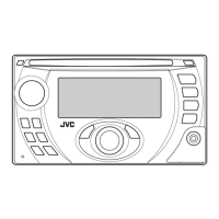
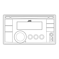
3.1.1 Removing the Front panel (See Fig.1)
(1) Remove the two screws A attaching the both side of the
Front panel.
(2) Disengage four hooks a engaged both side of the Front
panel.
Fig.1
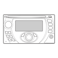
3.1.2 Removing the Bottom chassis (See Fig.2, 3)
(1) Remove the two screws B attaching the both side of the
Bottom chassis. (See Fig.2)
Fig.2
(2) Remove the three screws C attaching the Bottom chassis.
(See Fig.3)
(3) Remove the two screws D and two screws E attaching the
Heat sink. (See Fig.3)
(4) Remove the three screws F and one screw G attaching the
Rear bracket. (See Fig.3)
Fig.3
3.1.3 Removing the Main board (See Fig.4, 5)
(1) Remove the two screws H and one screw J attaching the
Side plate. (See Fig.4)
Fig.4
(2) Remove the three screws K attaching the Main board. (See
Fig.5)
(3) Disconnect B-B connector CN501
of the Main board con-
nected the CD mechanism and Main board. (See Fig.5)
Fig.5
A hook a
B
DDEFFG
C
HHJ
K
K
CN501
 Loading...