1-10 (No.YA654<Rev.001>)
3.3 MEMORY IC REPLACEMENT
• This model uses the memory IC.
• This memory IC stores data for proper operation of the video and drive circuits.
• When replacing, be sure to use an IC containing this (initial value) data.
3.3.1 MEMORY IC TABLE
3.3.2 MEMORY IC REPLACEMENT PROCEDURE
1. Power off
Switch off the power and disconnect the power plug.
2. Replace the memory IC
Be sure to use a memory IC written with the initial setting data.
3. Power on
Connect the power cord to the wall outlet and switch on the
power.
4. Receiving channel setting
Refer to the OPERATING INSTRUCTIONS (USER'S GUIDE)
and set the receive channels (Channels Preset) as described.
5. User settings
Check the user setting items according to the "FACTORY
SETTING ITEM" table.
Where these do not agree, refer to the OPERATING
INSTRUCTIONS (USER'S GUIDE) and set the items as
described.
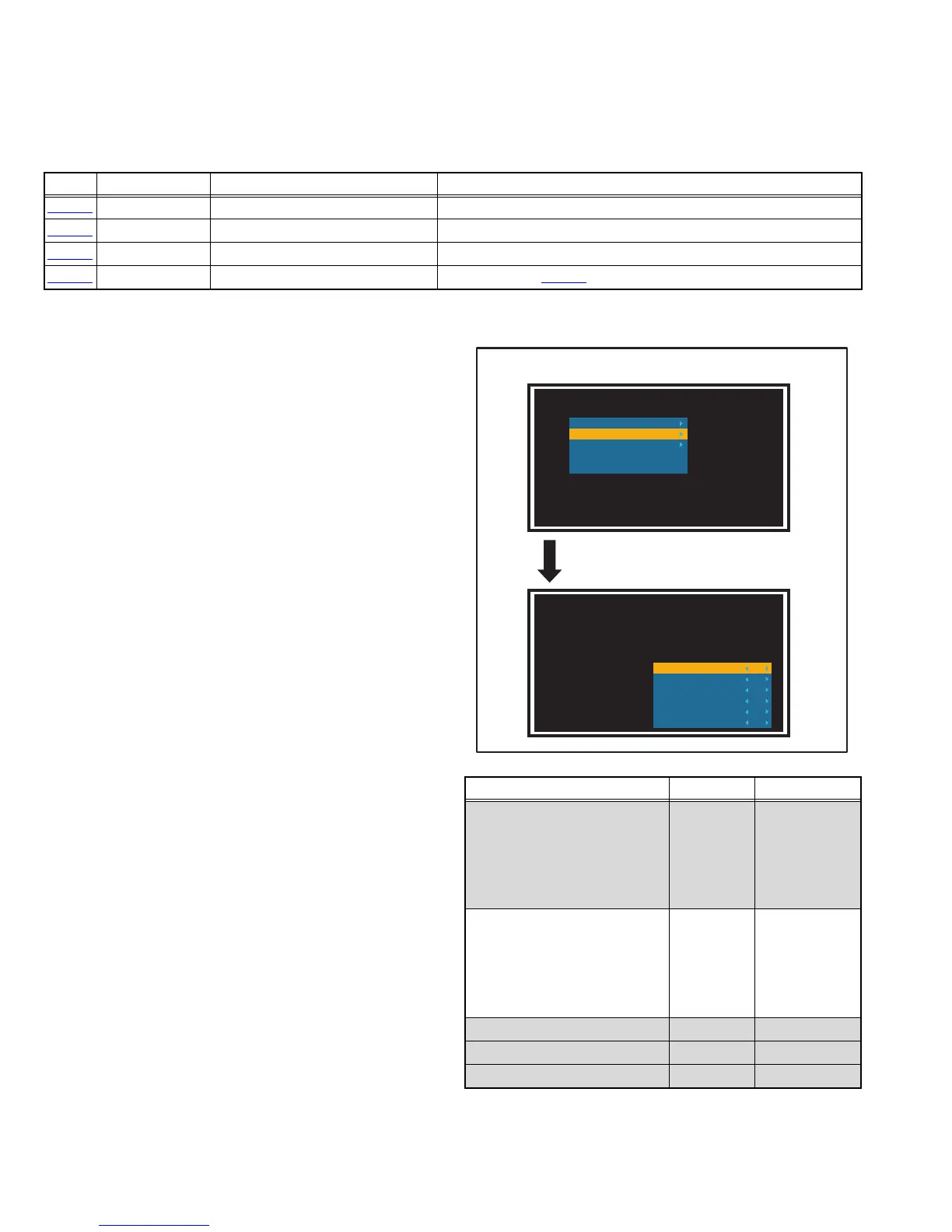
6. SERVICE MODE setting
Verify what to set in the SERVICE MODE, and set whatever is
necessary(Fig.1) .
Refer to the SERVICE ADJUSTMENT for setting.
3.3.3 SERVICE MODE SETTING ITEMS
Fig.3-4
Simbol Number of pins Mounting PWB Main content of data
IC2001
8-pin SIGNAL PWB Setting data of HDMI-1 is memorized.
IC2004
8-pin SIGNAL PWB Setting data of HDMI-2 is memorized.
IC2007
8-pin SIGNAL PWB Setting data of HDMI-3 is memorized.
IC2503
8-pin SIGNAL PWB Setting value of IC2501(SUB CPU) is memorized.
Setting items Settings Item No.
1.White Blance
Fixed
R Gain
G Gain
B Gain
R Offset
G Offset
B Offset
2.White Blance Base
Adjust
R Gain
G Gain
B Gain
R Offset
G Offset
B Offset
3.M16 EEPROM EDIT Fixed ---
4.I2C Stop Fixed ---
5.Version Fixed ---
Factory Menu
1.White Balance
2.White Balance Base
3.M16 EEPROM EDIT
4.I2C Stop
5.Version
R Gain
G Gain
B Gain
R Offset
G Offset
B Offset
0
0
0
0
0
0
Select the "2.White Balance Base".
SERVICE MODE SCREEN
 Loading...